Nano-porous SiN Lift-off with SU8 3010 Negative Resist
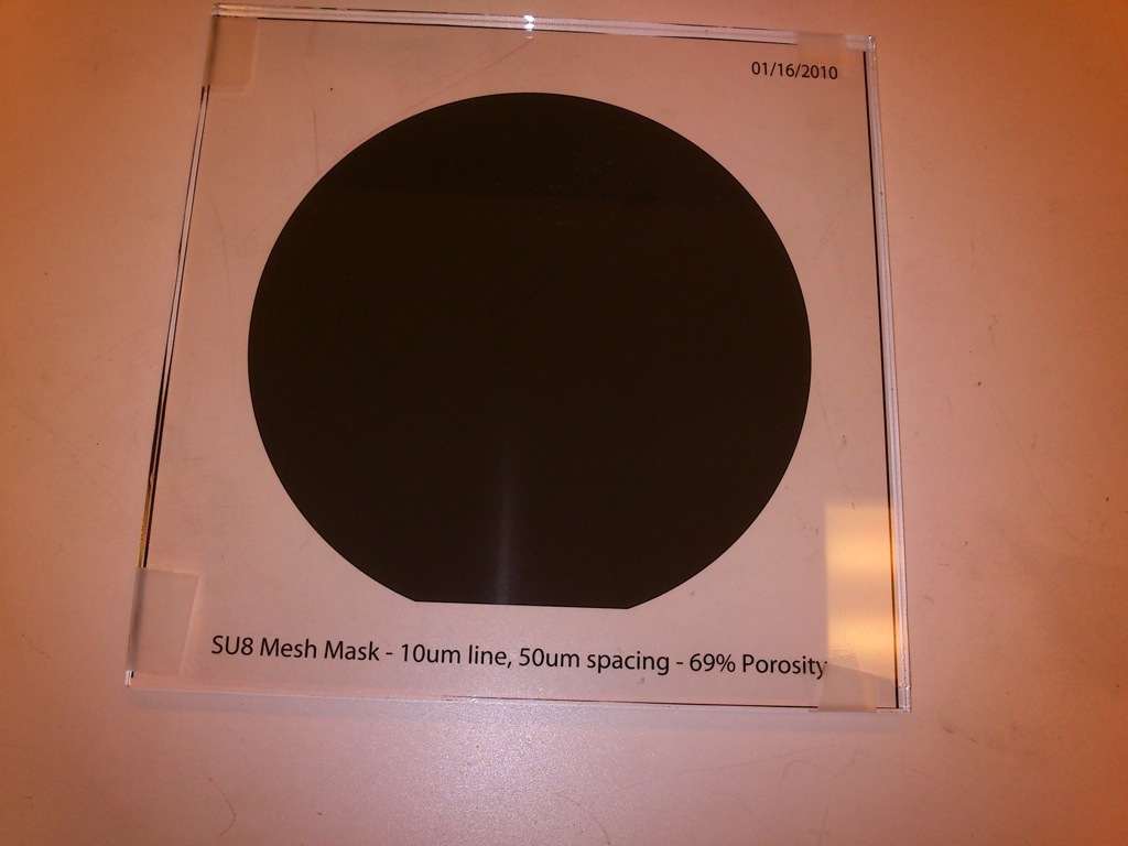
Using a wafer with a stack of Si-25nm(thermOx)-40nm(SiN)-50nm(PNCSi), lift-off was achieved on a small scale. First the SiN was etched using the standard process Simpore has developed, this also removed most/all of the PNCSi. The standard uChem process was then followed for SU8 application. A negative mask with 10um lines and 50um spaces was chosen for minimal etch times in BOE, see first figure.
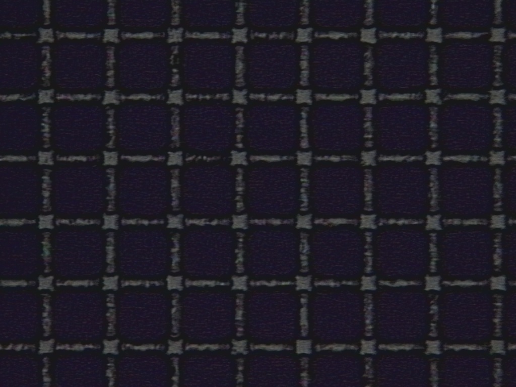
The exposure dose was increased for this experiment to 60 seconds, this over-exposed the SU8, however the grid was still sufficient for lift-off, see second figure.
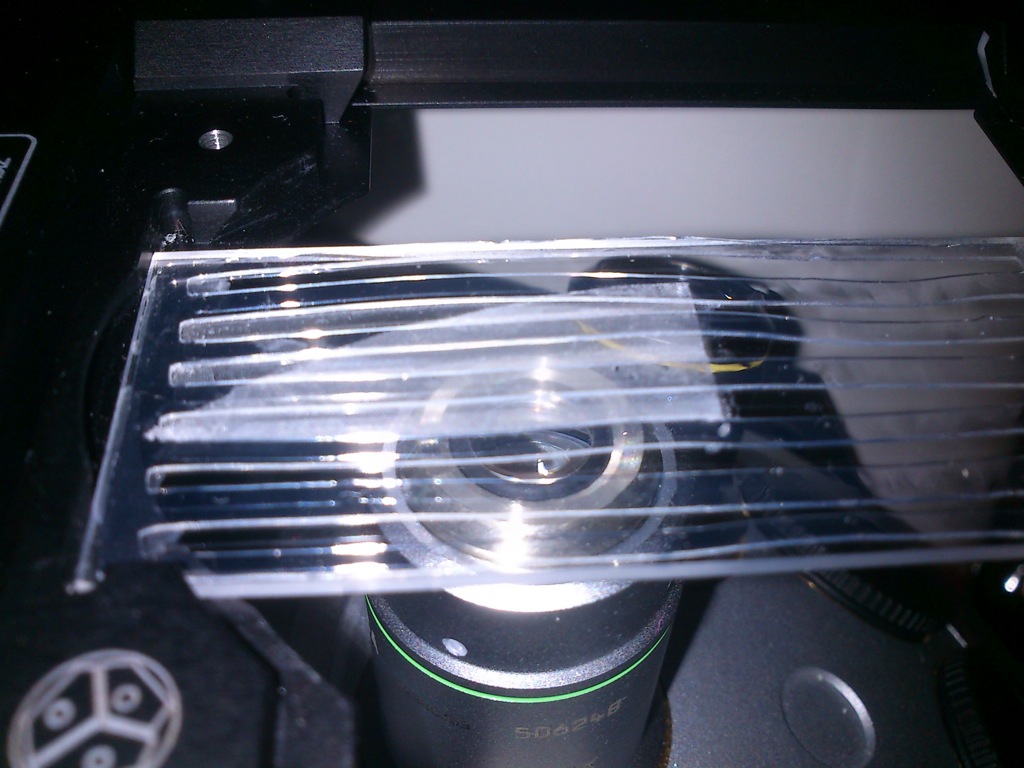
The wafer was then cleaved into small samples, each piece was used under different condition. First a fragment was placed in BOE (10:1) for 40 minutes (chosen based on TEM imaging of nano-porous material at 10, 20, 30, 40, 50, 60 minutes, and the estimated etch time to clear under the 10um lines). This sample appeared to have suffered clamping between the SiN and Si substrate, but looked promising, see the next figure.

Based on this image, it appears there is a membrane present, but much of it remained on the wafer fragment, and there was not an easy way to test its presence. The next fragment was to be placed in BOE for 30 minutes in an attempt to prevent clamping, and after lift-off a slotted microscope slide was used to remove from water.
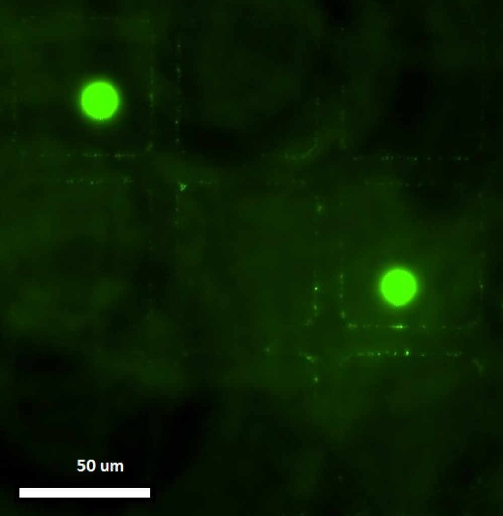
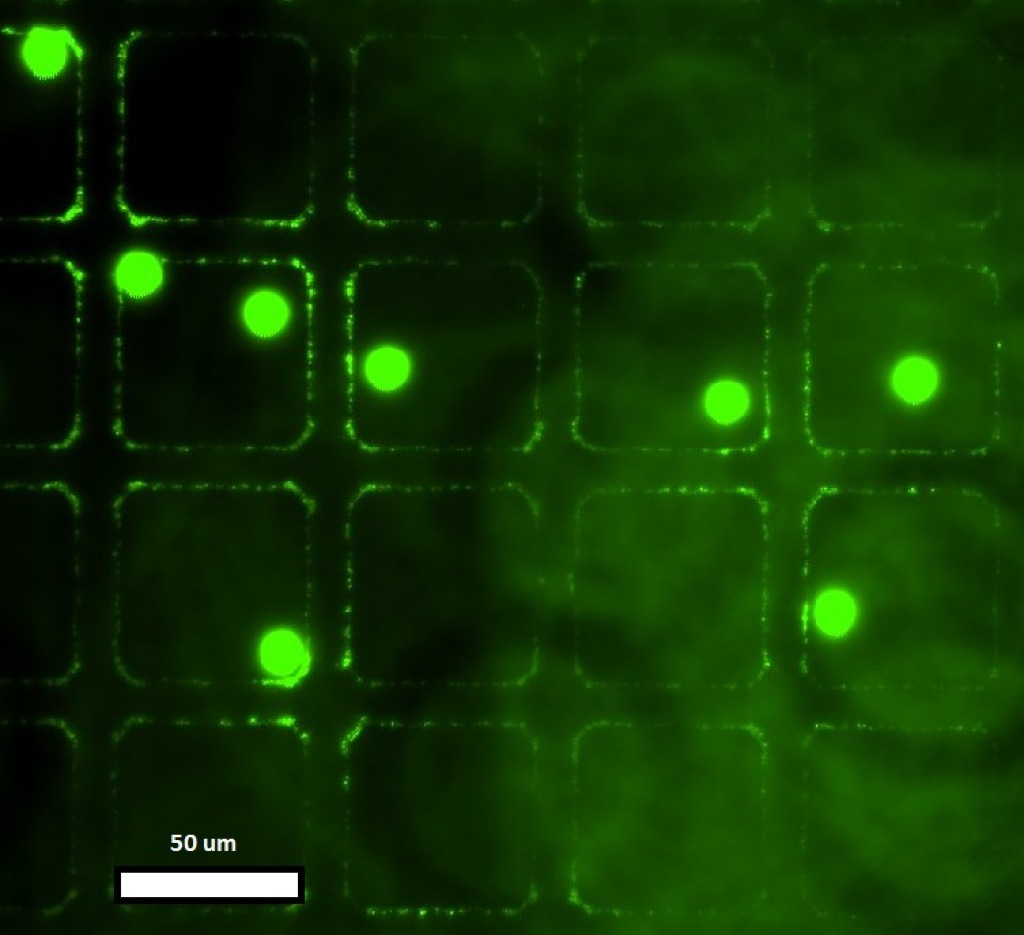
The capture slide was made with 300um silicone, with 2-3 mm slots running the length of the slide, this was to allow water to remain under the membrane. Once the fragment was removed from BOE, and placed in water, it appeared to have either retained all SiN-SU8 or none of it. In water the SiN is hard to detect, so florescent beads were deposited on the surface. If any beads stayed in the focal plane of the SU8, the membrane was still intact.
The results:
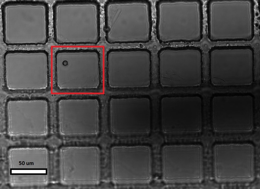
Some beads did sink to the bottom of the channels, but many stayed on top indicating an intact SiN membrane. This indicates there is tearing of the membrane during the current method, but not all integrity is lost during the handling. See the next figures of beads on the membrane.
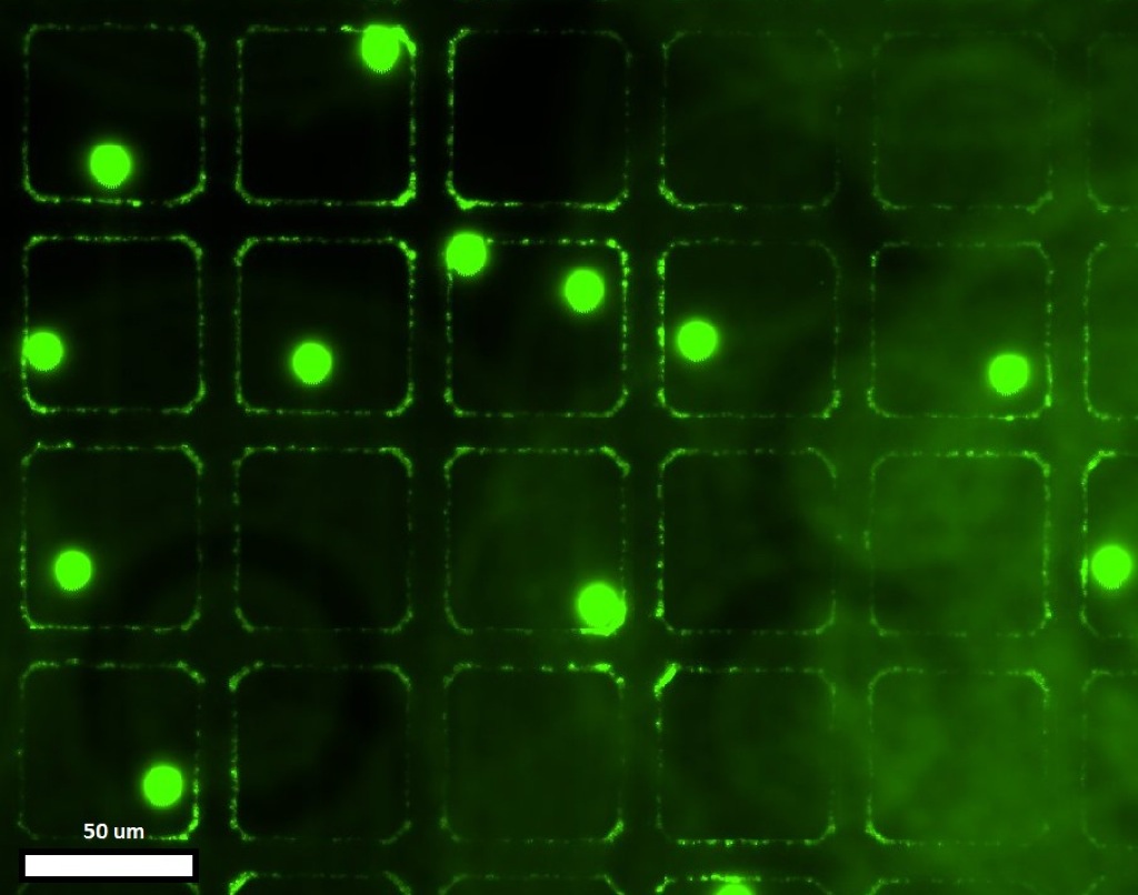
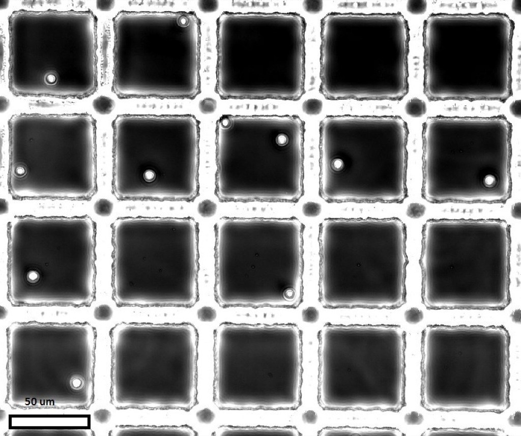
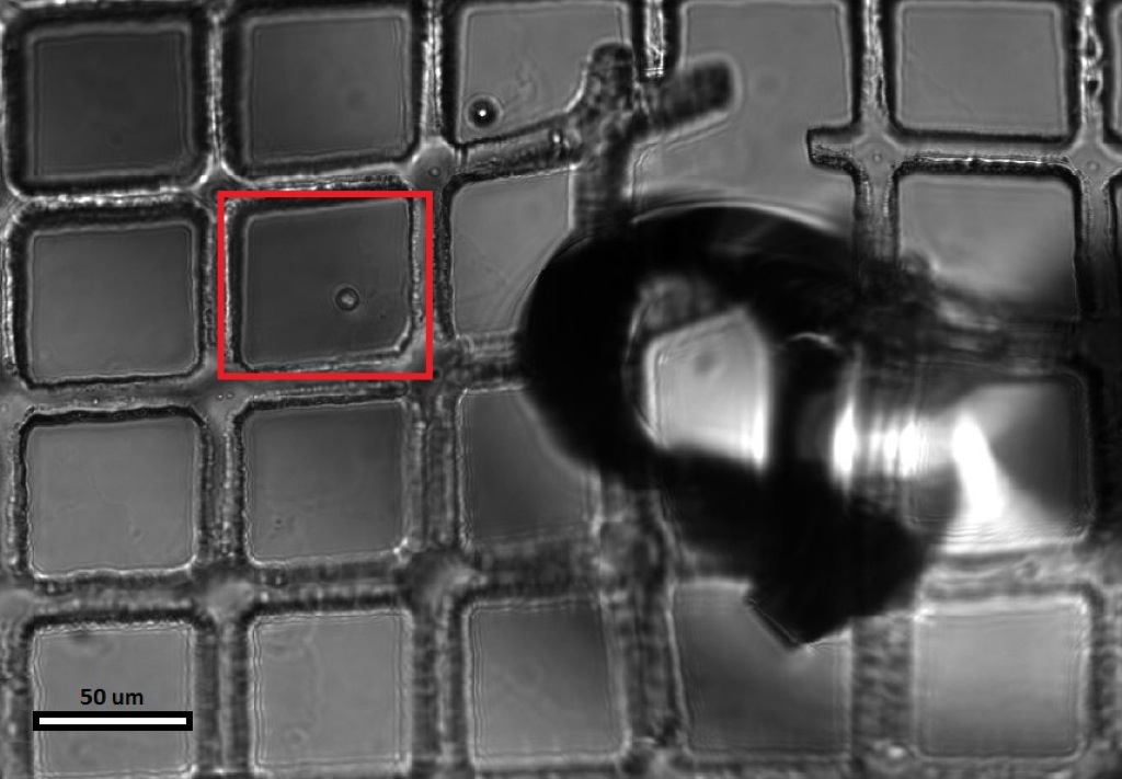
These figures show that the membrane does appear to be intact, however a micro prober was used to ‘poke’ the membrane, see the following figures. The first attempt to gently depress the membrane did not work, the probe crashed into the membrane breaking a large area (first figure below). then gentle pressure was applied and deformation occured, and finally a bead was imaged before and after contact to prove that it was resting on the membrane, not stuck to the SU8, or floating, etc…

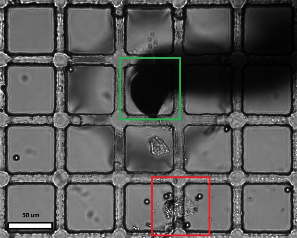
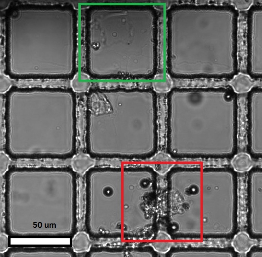
In the above figures, the Red indicates the first impact site, that did not cause massive damage to the membrane, the Green region shows the second impact point, in the second image, after the probe was moved, the membrane has been damaged.
Notice that the bead moves from one side of the membrane to the other after probe impact.
The results found here show that a large area membrane is achievable with lift-off and a polymer support structure. The next step is to develop a full experiment to optimize the stack, starting with the sacrificial oxide type, and thickness, followed by polymer optimization. The ideal sacrificial material will etch quickly in BOE and maintain uniformity across the wafer. We will be testing thicknesses of 25nm and 150nm for the oxide under the standard 40nm SiN, the three types of oxide to be investigated are Thermal, TEOS, and Sputtered.