Ozone Bonding Vincent’s Chips SEM

We have wondered if we can skip anodic bonding and bond the chips using our UV ozone process. There are pros and cons to this approach, mainly that the setup and procedure is easy, but the contact and alignment is difficult. So I gave it a try.


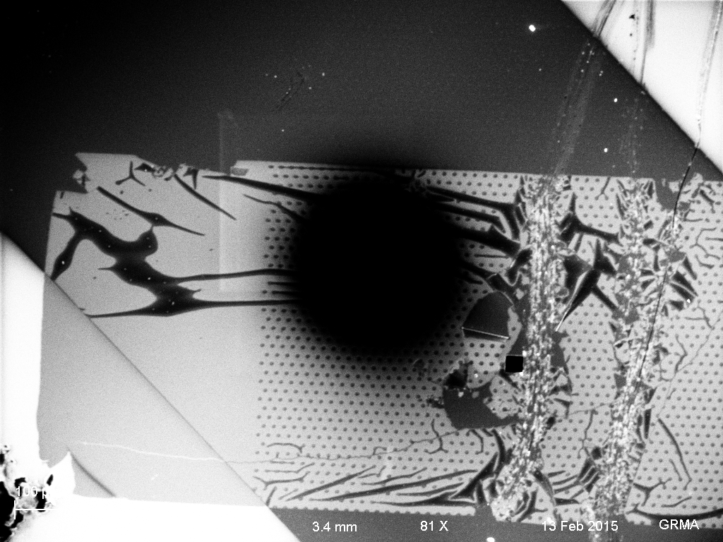
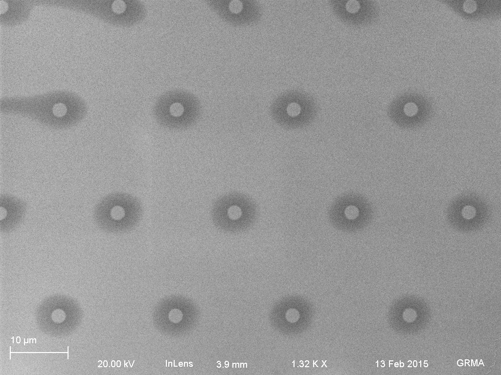
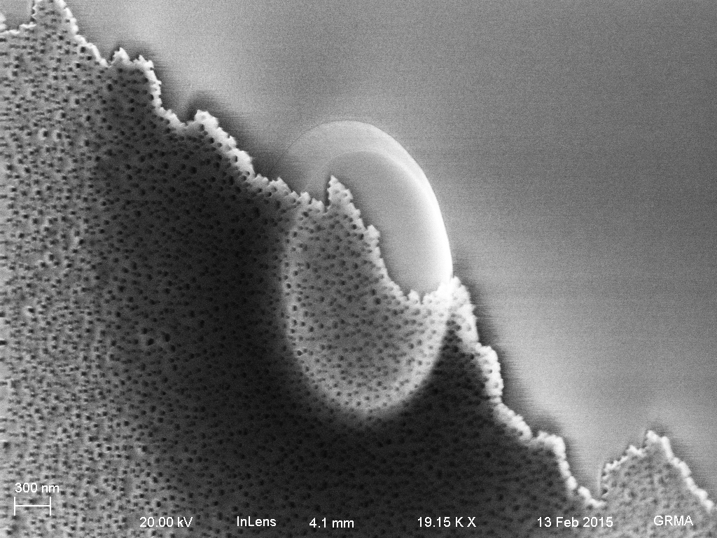
Here are a few SEMs of ozone bonded chips (oxide spacer to NPN flow chip, having previously been RTP’d at 700C to make ozone compatible). The chips were exposed for 10 minutes, then placed into Vincent’s clamp. I left the chip combo with pillars over 24 hrs in the clamp at room temperature, and I left the chip combo without pillars for 3 hrs in the 70C oven. The chips fell off of each other upon removal from the clamp.

Chip with pillars

Ozone_bonded_air_clamp_00
NPN on top of pillars. The black spot is the backscatter detector, ignore it (no signal). Dragged tweezers across the area to create some damage and see how well the membrane bonded.
Ozone_bonded_air_clamp_02
20 nm nitride window for electropore drilling was ruptured. Possibly due to my tweezer scratch. NPN material is stacked around edge.
Ozone_bonded_air_clamp_04
Unruptured npn on top of posts. The dark circles are bits of the membrane draped over the posts, coming down to contact the bottom 20 nm nitride membrane (air pockets). The average radius from the edge of the pillars is between 2-3 microns (n=10).
Ozone_bonded_air_clamp15
45 degree view. The tweezer damage shows membrane rupturing and taking some of the pillars with the rupture. The bond between the oxide and nanoporous nitride appears to be stronger than the 20 nm nitride and the silicon underneath.
Ozone_bonded_air_clamp_12
45 degree view. Crossection of oxide post and draped NPN over top.
Ozone_bonded_air_clamp23
45 degree view. Contiguous post/membrane surrounded by NPN.


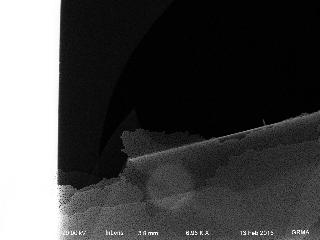
Chip without pillars

Ozone_bonded_HEAT_CLAMP01
The flow chip NPN membrane remains mostly intact across the oxides, but sags down to the surface. The sagging probably caused the cracks along the edges of the oxide (wrinkles at the top boundary), as more bonds were formed.


Overall, the freestanding material kept its shape during the bonding process, displaying sharp edges. The rest of the bulk material did not bond as well; the pieces separated by simply tilting the two chips.


In the future, we will need to redesign these chips with tightly spaced posts, whether we use anodic bonding or ozone bonding. The amount of flexibility inherent to this 50 nm film is incredible.


Similar Posts