Single Channel Dialyzer
The main difficulty with creating a simulation of the single channel dialysis chip is that the membrane is so very thin (20 nm). This is especially true when compared to its length of 10 mm but also when compared to the channel depth and permeate well (which in our case is actually a beaker of water, more of this anon.) I ameliorate this difficulty by using localized scaling. The membrane is drawn 1000 times thicker than its physical dimensions and the Diffusion Coefficient, Dm, is increased to account for this. So the thicker membrane filters particles at the same rate as the thinner physical membrane. So the diffusion in the membrane region, Dm, is scaled by (1/scale). There is no scaling in the other two regions, and no convection in the membrane. COMSOL has an example of scaling the entire model in one dimension and used (1/scale2) factor, I believe this is an error as the diffusion coefficient is differentiated once and not twice as they claim. To test my proposition I modeled a 2D diffusion with a variable membrane thickness which I scaled by scale, scale2, and scale1/2. The diffusion coefficient Dm = Df/F0, where Df is the free diffusion and F0 is a formation factor defined by F0 = 1/(nt) [1], where n = porosity, t=tortuosity. For our membranes t is assumed to be unity.
I set up a 2D model with three regions.
1. Retentate channel: 300 µm deep (tall), 10 mm long
2. Membrane: 20 µm thick, 10 mm long (scale = 1000)
3. Permeate well: 1 mm deep, 10 mm long

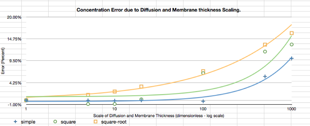
Simulations were run using three scaling schemes, scaling by (1/scale1/2), (1/scale), and (1/scale2) with scale = 0.5, 1, 5, 10, 20, 100, 500, and 1000. (Figure 2 shows that for scaling factors up to 100 produce negligible error for the simple multiplicative case. This allows for a drawn membrane thickness of 2-µm thick membrane which COMSOL can handle much better than a 20-nm thick membrane.
The analytical solution, from the infamous “Permeabilities.numbers” spreadsheet, indicates that with a Péclet number of one, where the concentration at the outlet should be ~32% the initial concentration (68% reduction in the retentate), occurs for flow velocity of 0.62 mm/sec. This solution does not take membrane permeability into account and all particles reaching the bottom of the channel are assumed to pass into the permeate. Our 2D COMSOL simulation. Dm = 1.4×10⁻⁹ m2/sec, Hm = 20×10-9 m (Dm is scaled in the membrane region)
These values result in a dialyser output concentration of 46% of the initial concentration.
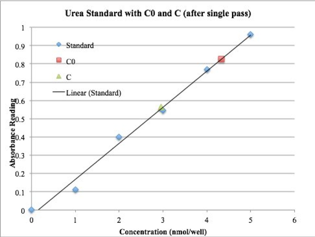
Experimental results for single channel dialyzer submerged in a stirred beaker of DI water with urea pumped at 5.6 µL/min. This rate was determined by setting the Pé clet number to one. The reduction in urea in the dialisate (retentate) was 32% leaving 68%. This is about half of the goal reduction, which assumed that all of the urea diffusing to the membrane would be filtered without hinderence from the membrane permeability. To sum thus far, analytically we predicted 68% reduction, COMSOL predicted 46% reduction, we actually saw a 32% reduction.
An additional experiment with a slower flow rate (2.8 µL/min) is currently planned to verify the effect of flow rate on urea filtration.
[1] Cornell, D., Katz, D.L. 1953 “Flow of gases through consolidated porous media” Ind. Eng. Chem. 45 2145-2152
Blood Urea Nitrogen, BUN, levels range from 7 to 21 mg/dL for healthy adults. This converts to 2.5 to 7.5 mmol/dL of urea. Our experiments used 0 to 10 nmol/50-µL well or 0 to 20 mmol/dL