The Enemy Within: Optimizing an OLCN PUA Coated Microporous Membrane Mimetic and Exposing an Unlikely Saboteur
The battle for soft membrane coatings wages on as we continue to optimize polyurethane acrylate (PUA) coatings for our osteomyelitis project, whose background is described here and here and initial progress is described here. Since our last update, we have honed in on our most promising recipe and tried to fine tune its settings in order to produce our desired surface morphology (smooth) and thickness (1 um). We have also begun to refine our back through pore etch, producing surprising results along the way. These efforts together seem to be leading us closer and closer to our desired final product, but progress has suddenly come to a halt. Read on to find out why, and how we plan to move forward.
Flat Side Etches
Out of all of the different etch recipes we have tried in the past, a mixture of oxygen and argon gas seems to give us the best results. As a result, the majority of the flat side etches that we tried this time around are a combination of oxygen and argon gas at the same ratio (25 sccms of oxygen and 50 sccms of argon) but at varying powers. The results for each flat side etch are shown below and labelled flat side etch (FSE) 1 through 7. Two etch recipes are done twice. Their first attempts are labelled ‘a’ and their second attempts are labelled ‘b’.
O2-50 sccms etch at 150 W for 2 minutes (FSE-1)
Previously an etch recipe using just argon gas at 50 scmms and 150 W forward power initially gave us a great smooth polymer surface. Unfortunately when we lengthened the etch time with this recipe, the chamber heated significantly and our polymer coating melted. To see if we could get similar results but with oxygen gas instead of argon (with the hope of oxygen etching our polymer more quickly), we tried this one. While this etch did thin the polymer much more quickly, in fact more quickly than any other etch recipe attempted at this point, it did not produce a good surface morphology. Like other etches which were too aggressive and anisotropic, the top surface of the PUA is covered in small peaks.
Surface Morphology
Thickness
O2/Ar-25/50 sccms etch at 110 W for 7 minutes (FSE-2a)
Out of all of the recipes attempted up until this point, this etch brought our PUA the closest to our target thickness of 1 um. Despite this, the surface morphology is not ideal as it is covered in small polymer peaks.
Surface Morphology

Thickness
O2/Ar-25/50 sccms etch at 80 W for 10 minutes (FSE-3a)
This etch recipe created one of our best surface morphologies while also getting the polymer close to our target thickness. With very limited surface roughness, these results were very promising.
Surface Morphology

Thickness

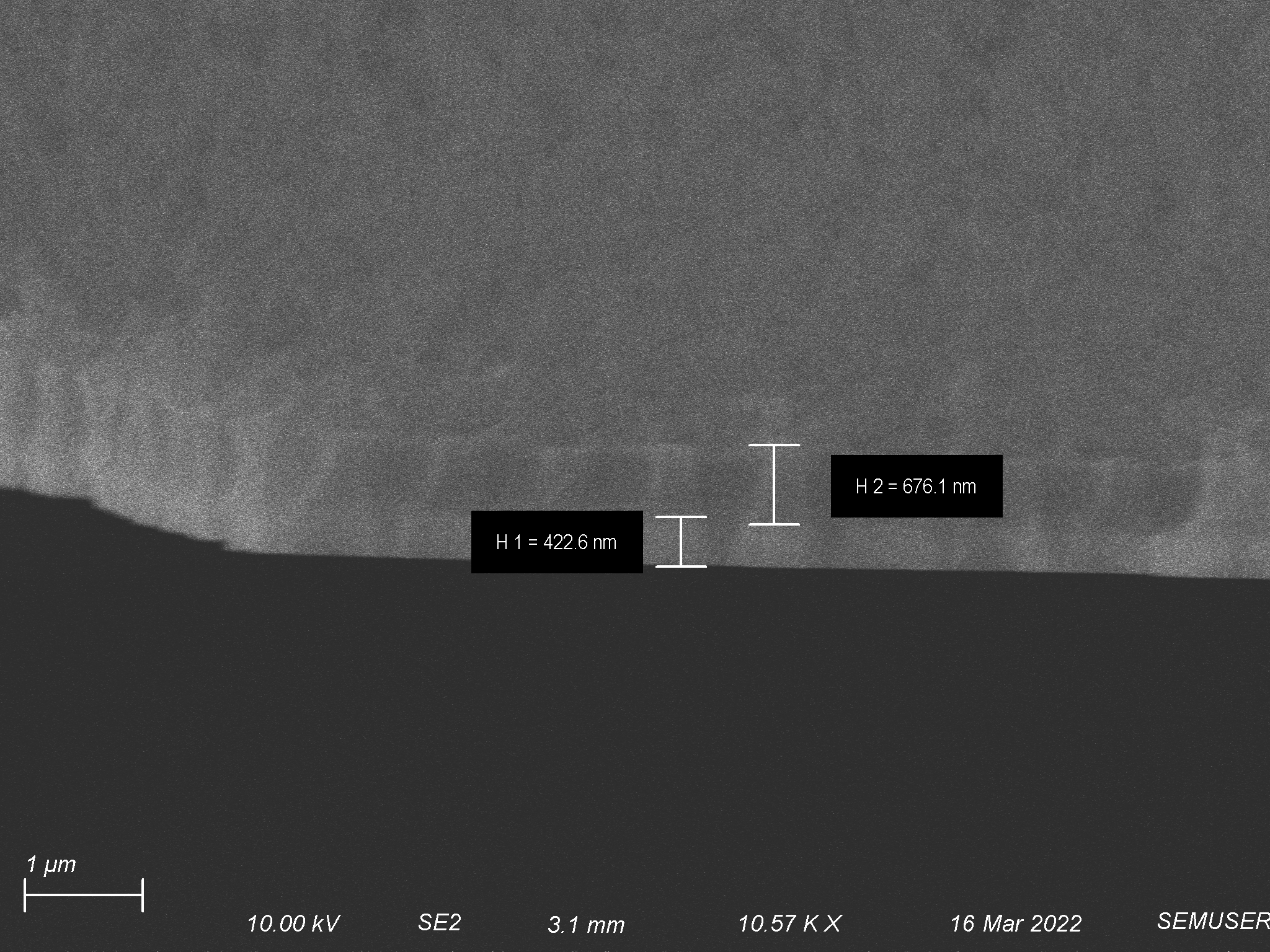
O2/Ar-25/50 sccms etch at 70 W for 10 minutes (FSE-4)
When I did this etch I intended to use 80 W for 15 minutes, but I had trouble getting the RIE to create a steady plasma at that power. Because of this I had to settle for 70 W and only got a steady plasma with 10 minutes left in my etch. Surprisingly, this gave us very good surface morphology. Unsurprisingly this also resulted in less material getting etched away, putting us further away from our target thickness.
Surface Morphology
Thickness
O2/Ar-25/50 sccms etch at 80 W for for 15 minutes (FSE-5)
This time around I actually did get the RIE to set a steady 80 W plasma for 15 minutes. Unfortunately, this was too long for the PUA and it was almost completely etched off of the membrane.
O2/Ar-25/50 sccms etch at 80 W for 11:30 minutes (FSE-6)
Seeing that a 10 minute etch using this recipe did not take away enough polymer and a 15 minute etch using this recipe took too much polymer away, I next attempted to find a happy medium between the two. After etching for 11:30 minutes we did get closer to our target thickness (1 um), but our surface morphology was not ideal.
Surface Morphology
Thickness
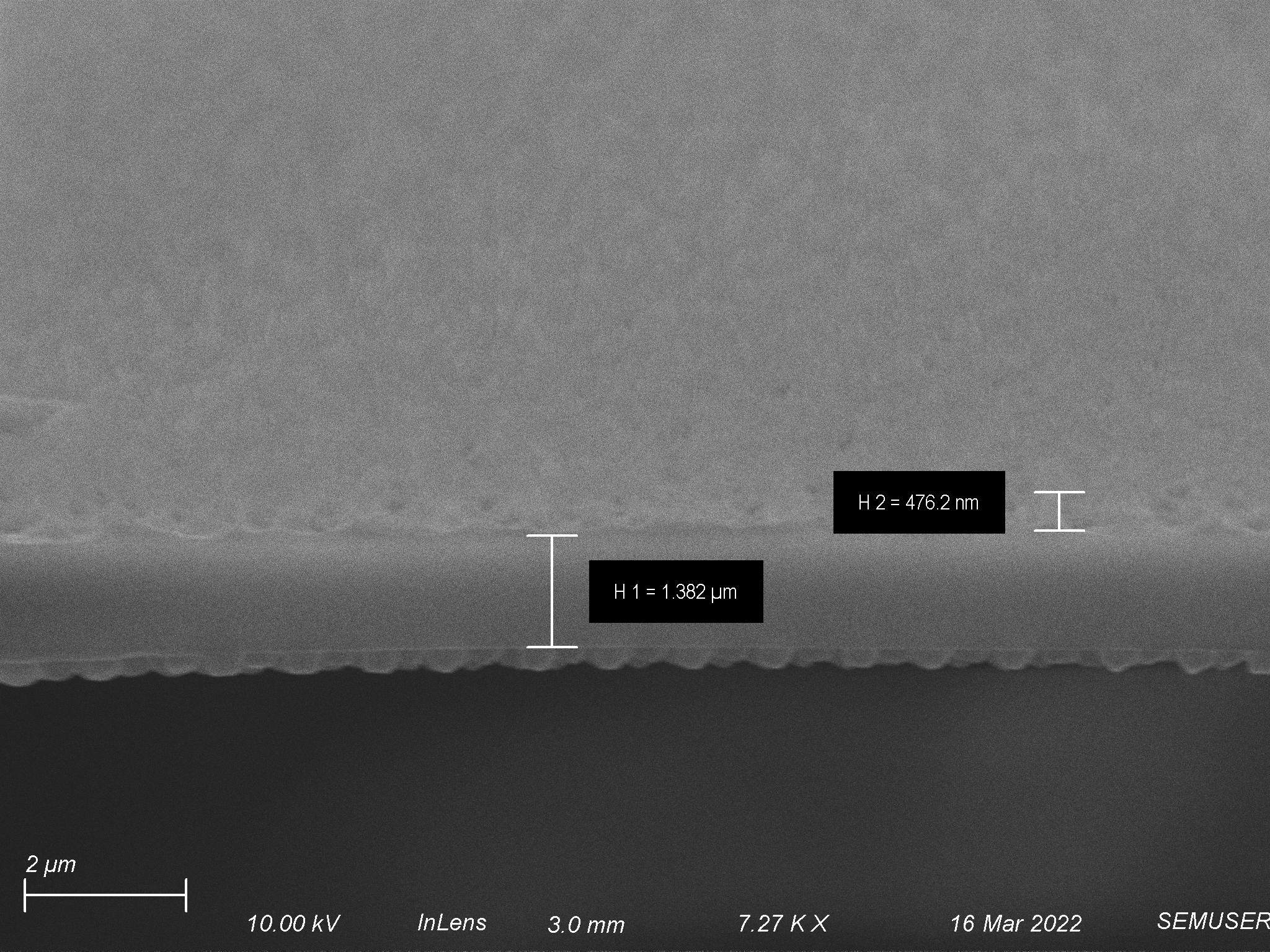
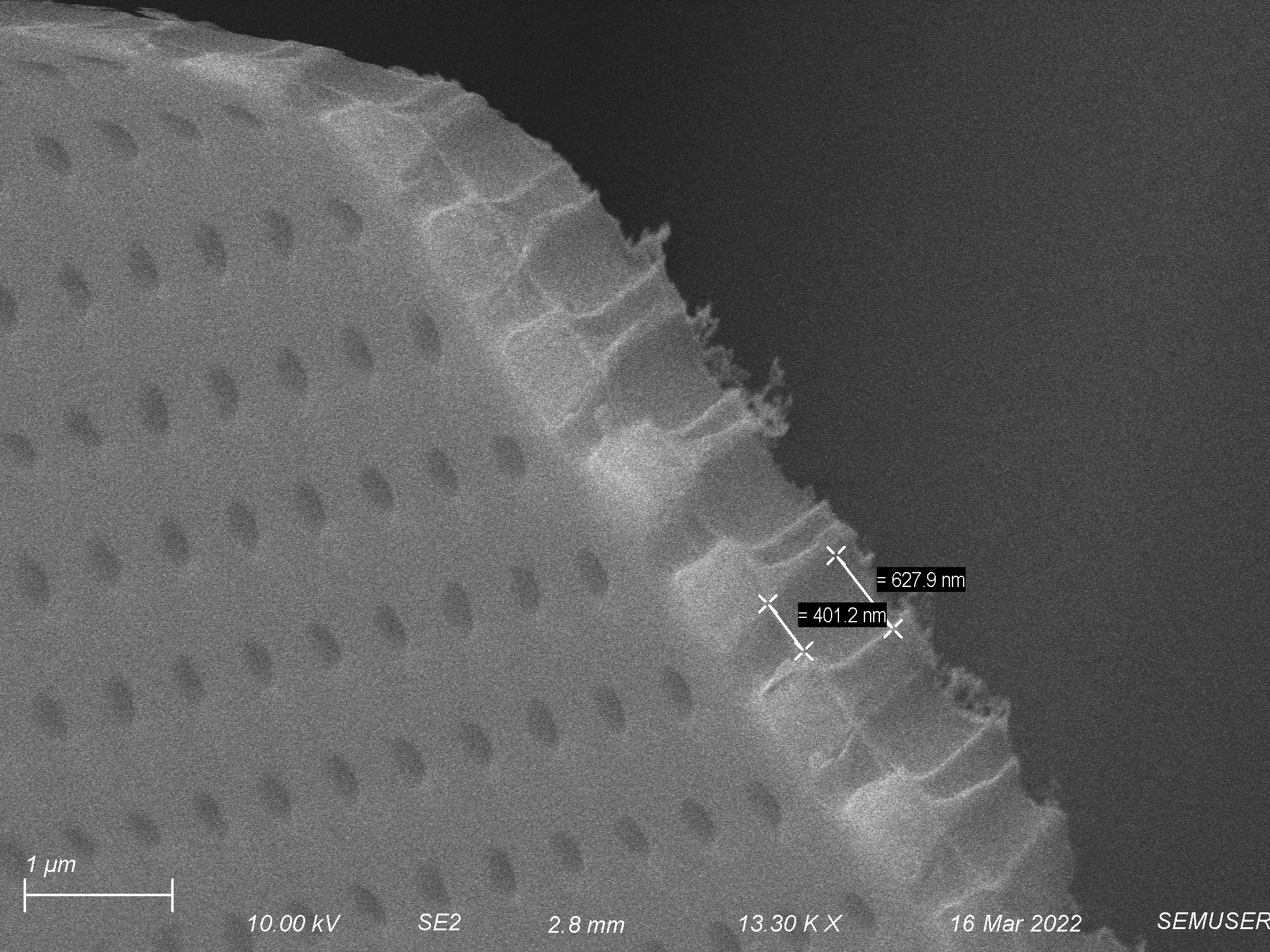
O2/Ar-25/50 sccms etch at 70 W for 15 minutes (FSE-7)
Seeing that we may not get down to 1 um using 80 W of power while maintaining a smooth surface morphology, I next tried to decrease the power to 70 W as previously this gave us very smooth surface morphology. Knowing this would etch away less material, I extended the time of this etch back to 15 minutes. Compared to the last 70 W etch, the surface of the polymer was rougher this time around. Surprisingly, the polymer was thicker this time around despite the fact that I etched longer. This began to clue me into an issue which affects the next two etches: the PUA begins to “go bad” from this point onwards. This was not confirmed until later, but I was towards the end of my vial which had been supplied to me at the beginning of this project and the polymer was acting differently than before. Whether the cause was undissolved PUA at the bottom of the vial or a concentration difference as THF evaporated over time (I noticed PUA leached out of the glass vial over time, covering the outside in sticky residue) the polymer was more viscous now than it was before. Because of this my initial deposition was thicker than I thought, causing the flat side etches to create polymer layers that were etched similarly to before but thicker overall. This explains why we got the results shown below.
Surface Morphology
Thickness

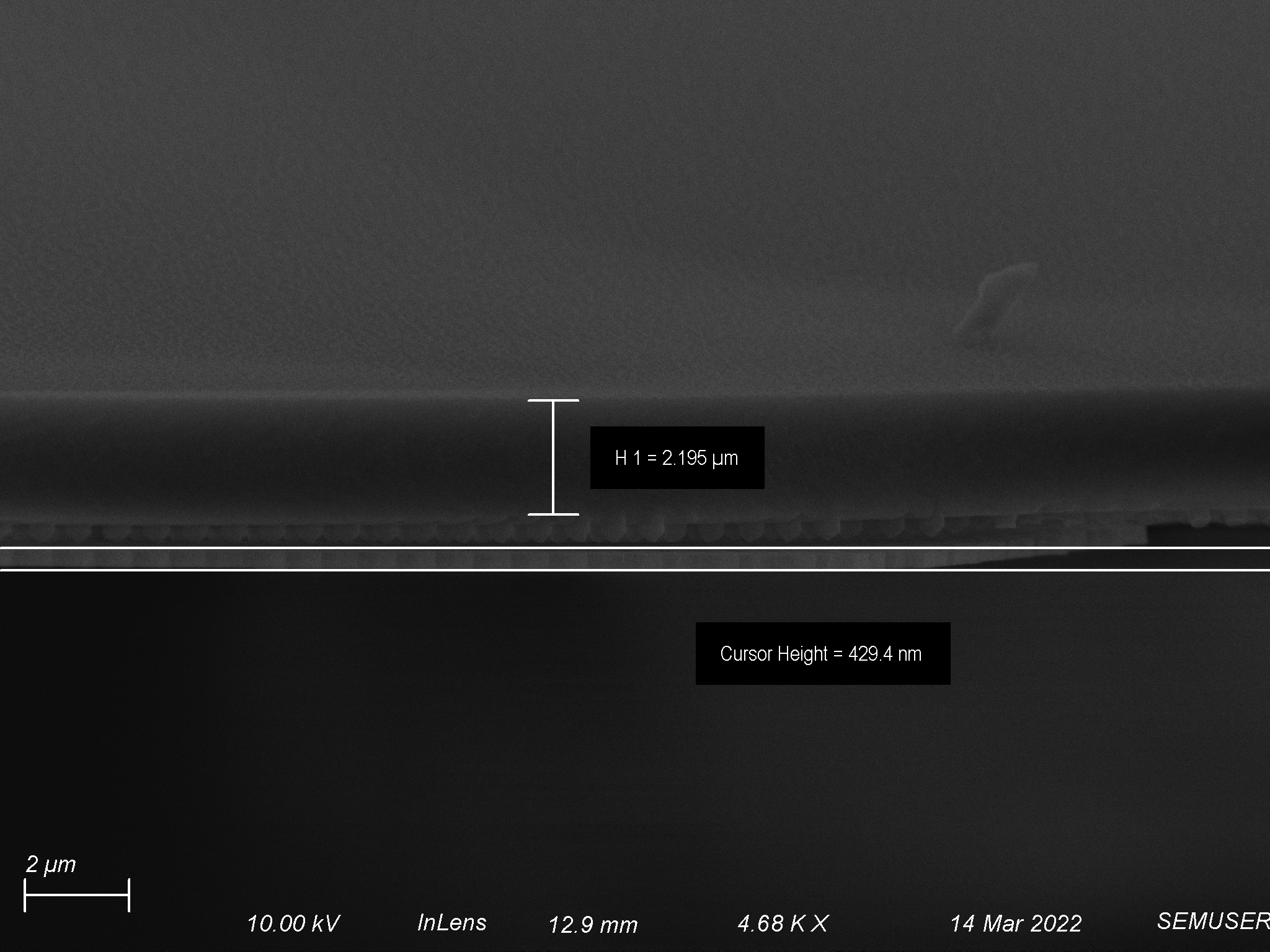
O2/Ar-25/50 sccms etch at 80 W for 10 minutes (FSE-3b)
At this point I did not know that the polymer had gone bad, and seeing that 70 W was not giving me reasonable results I decided to try to use my newfound knowledge about back side etches cleaning up surface roughness and thinning layers that were close to 1 um in thickness on my best two recipes. This flat side etch previously gave me my best surface morphology at ~1.7 um thick, so I thought if I reproduced the layers that it made before I could use the back side etch to thin it the final 0.7 um down to 1 um total. This would ideally produce a 1 um thick polymer layer which had a smooth surface. Unfortunately this time around the surface was slightly rougher but most importantly, the polymer was much thicker overall. This again began to clue me in to the fact that the polymer was going bad, but I still did not know this for sure.
Surface Morphology
Thickness
O2/Ar-25/50 sccms etch at 110 W for 7 minutes (FSE-2b)
Taking the same approach as described in my last flat side etch, I wanted to reproduce the results I saw with this etch since it got me the closest to our final target thickness of 1 um at the cost of a relatively rough surface. If done properly, the back side etch would theoretically clean up the surface and make it smooth and I would end up with a 1 um polymer coating with a smooth surface. This time around the surface morphology look very similar to what I had gotten before. Unfortunately like my last etch attempt, the polymer was much thicker overall. Being the second time this had happened I knew something was not performing as it had in the past. My first instinct was the RIE since I had issues with it in the past, but while talking with Sam he brought into question the quality of my PUA since I had been complaining about it leaching out of its vial. Another clue I observed while imaging was a slight decrease in layer uniformity. Up until this point I had seen fantastic uniformity in my depositions, but in this layer some areas were thicker than others. It was most noticeable after the back etch when I saw some areas were etched though but others were not. This last observation led me to question the quality of my PUA before the RIE chamber, because of the aforementioned but also because the back etch seemed to work fine.
Surface Morphology
Thickness
Back Side Etches
Some of the first flat side etches that we tried at the beginning of this project failed because they were too anisotropic. While we need a more isotropic etch for the flat side, we need an anisotropic etch for the back side in order to maintain a high fidelity pattern transfer of our pores to the polymer. Therefore, we revisited the original more anisotropic recipes for use in our back side etch. The results were surprising and are shown below. Each backside etch was done on the back of the product of the flat side etch whose label is in the tile of each back side etch.
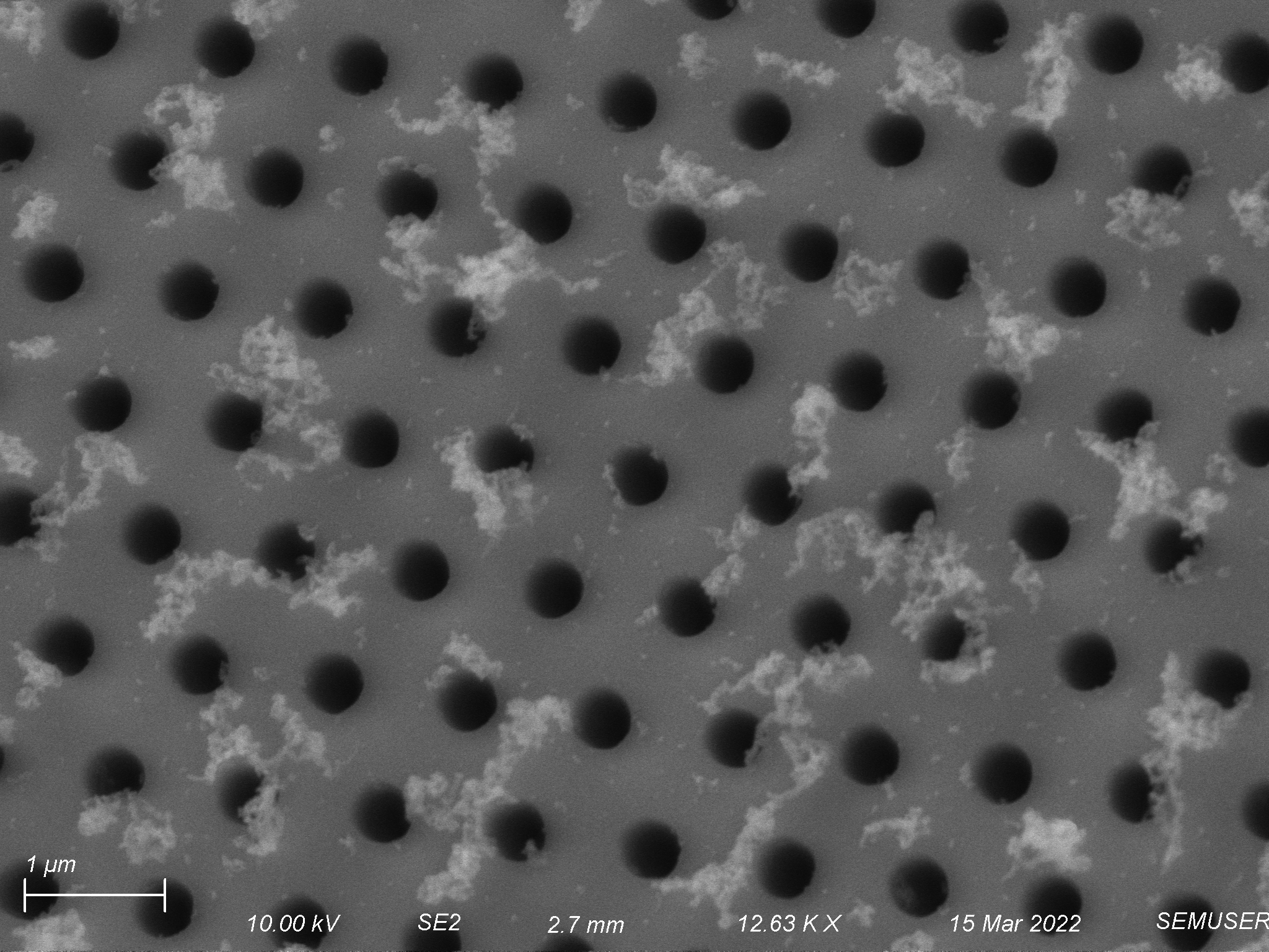
O2/Ar-12.5/12.5 sccms etch at 150 W for 5 minutes (on the back side of FSE-4)
In the past, this recipe was our most anisotropic as a flat side etch. Therefore we tried it as a backside etch to see how it would do. Depth-wise we did not make it very deep into the polymer. In terms of pore morphology the etch performed well, making straight tunnels with diameters similar to the pores of the membrane.
Pore Morphology

Depth


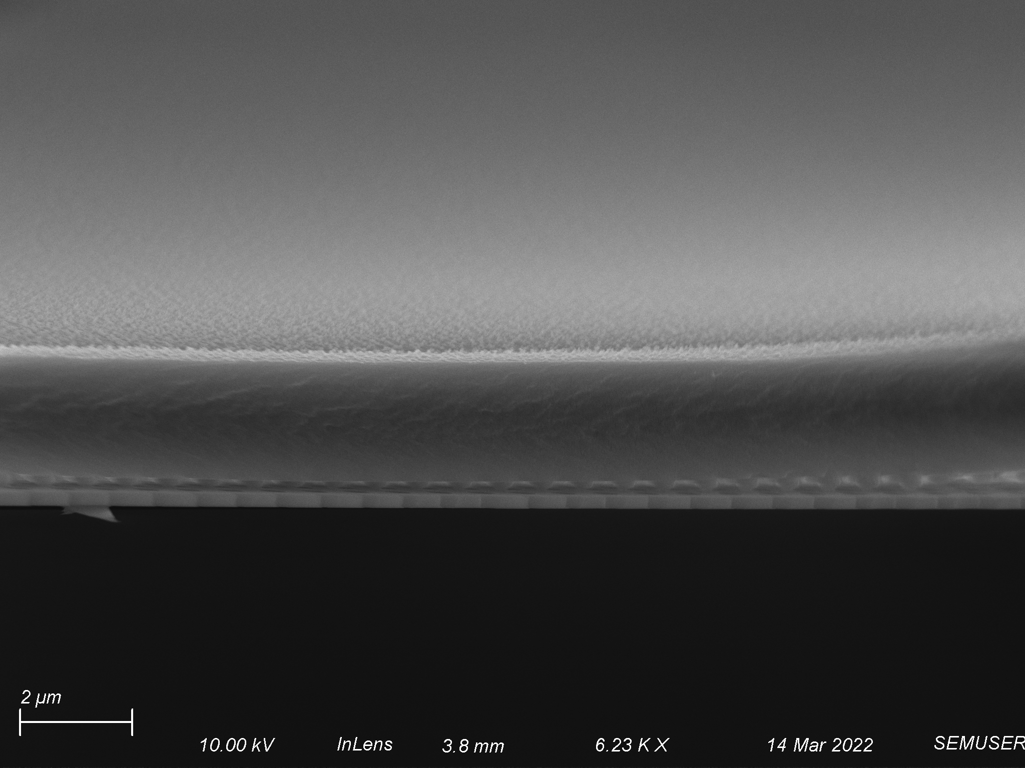
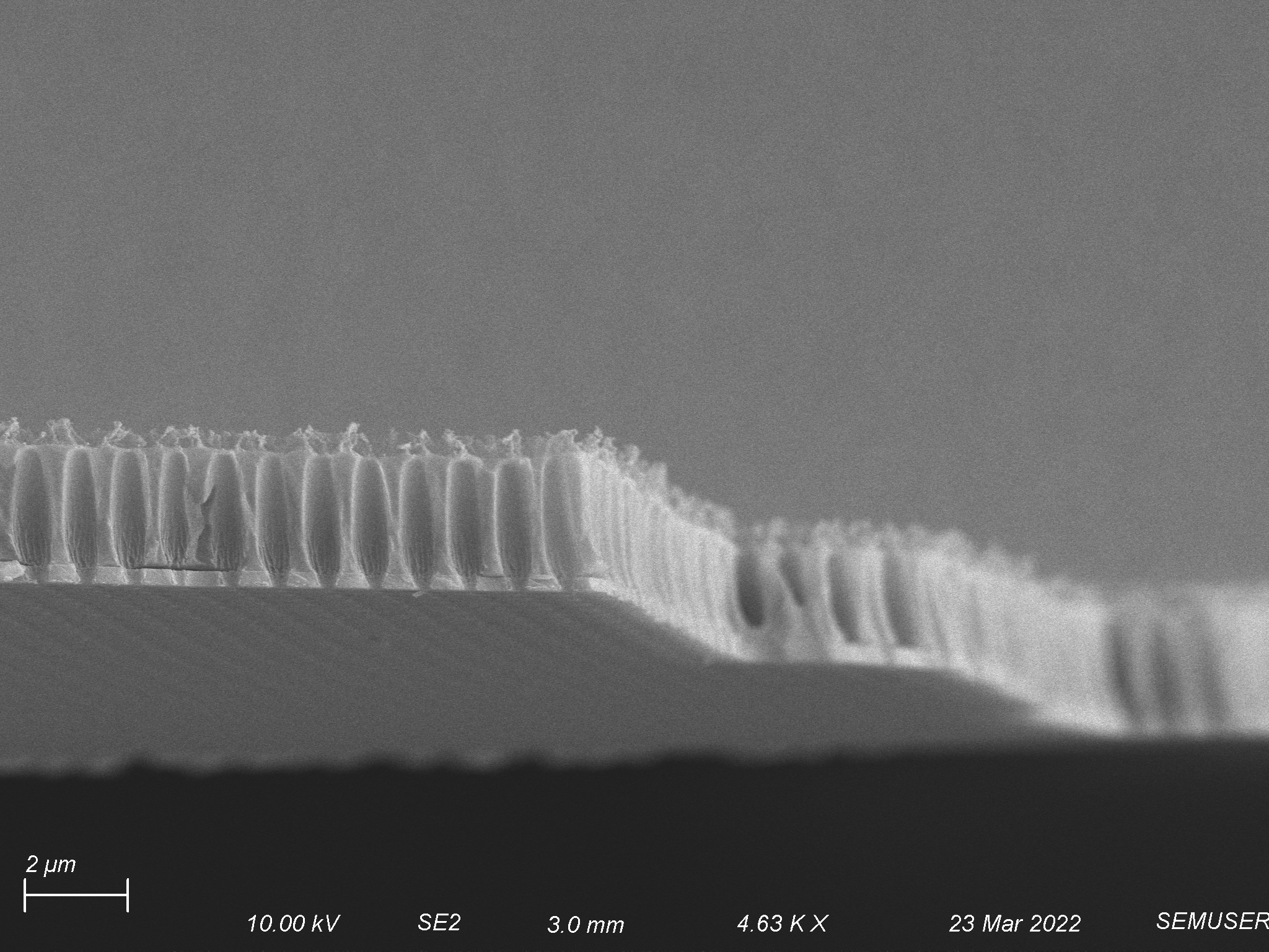
O2/Ar-12.5/12.5 sccms etch at 150 W for 10 minutes (on the back side of FSE-5)
After the flat side etch that was done on this polymer layer, there was not much to work with for this back side etch. Not much changed after it was done.
O2/Ar-12.5/12.5 sccms etch at 150 W for 10 minutes Round 2 (on the back side of FSE-6)
This is the same back side etch that we had previously attempted on the PUA which was almost completely removed from the membrane. Since we had no idea how it performed, I did it again. I doubled the length of this etch from the first time I did it to see how much further we would get into the polymer. Surprisingly, I found that not only did I etch all the way through the polymer that was on the membrane, but I also cleaned up some of the surface roughness that was on the top of the flat side etch and further shortened the polymer. This changed the way that I looked at the back side etch as I now knew that I could potentially use the flat side etch just to get close to an ideal polymer thickness and surface morphology, then clean up the surface morphology and further shorten the polymer hopefully to 1 um using the back side etch. Of course this requires being close to our desired surface morphology and thickness once the flat side etch is done since longer back side etches will blow out our polymer tunnels. Evidence of this is shown below when comparing the diameter of the tunnels in the polymer to the diameter of the pores of our silicon nitride membrane.
Pore Morphology

Depth
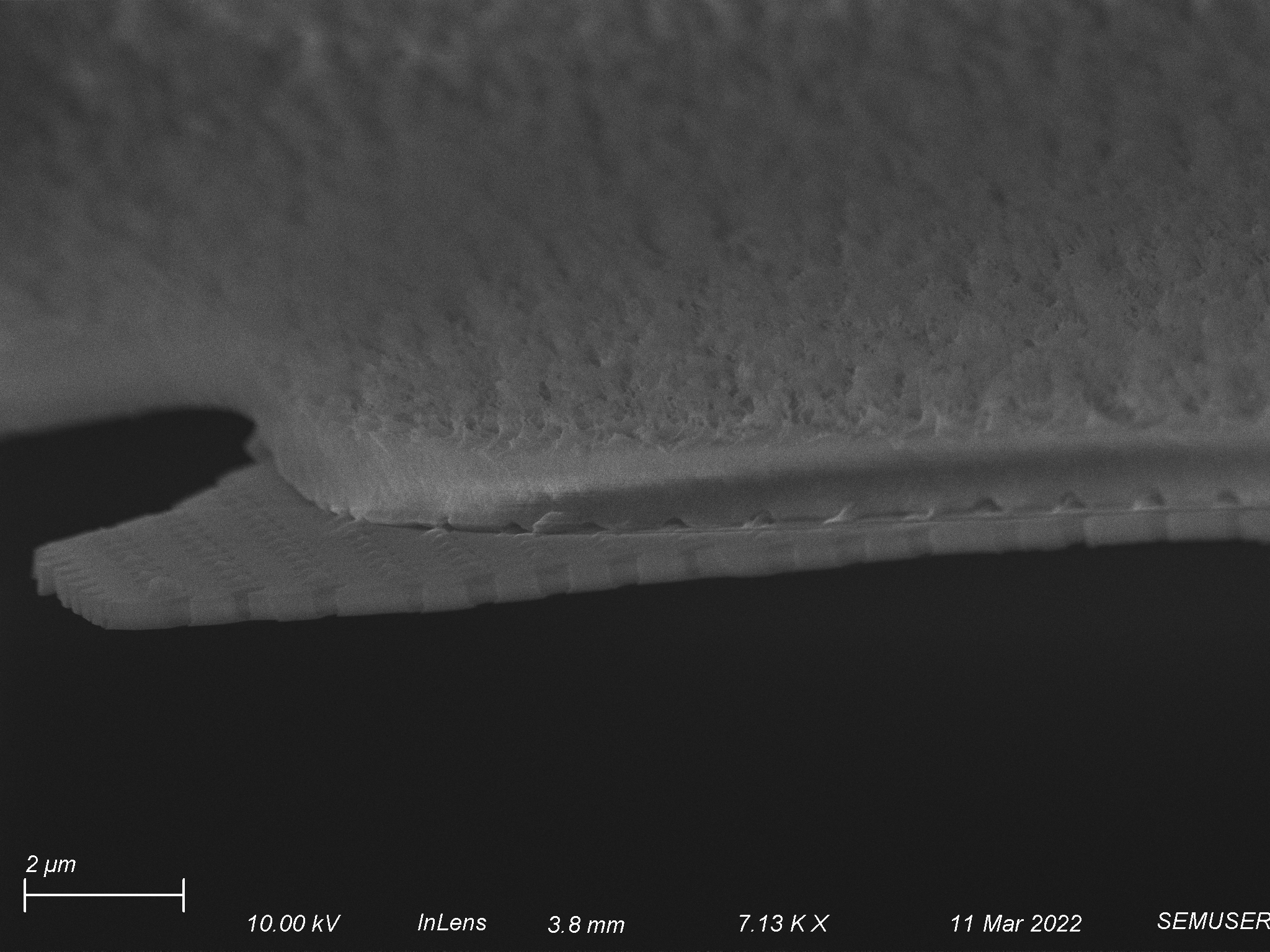
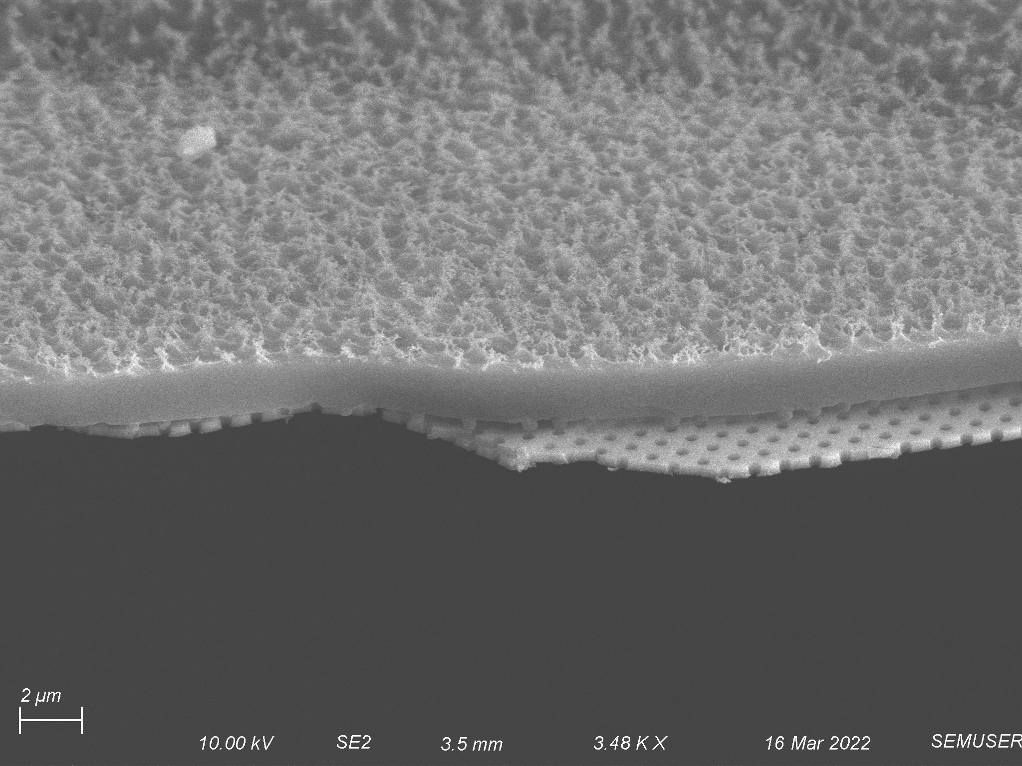
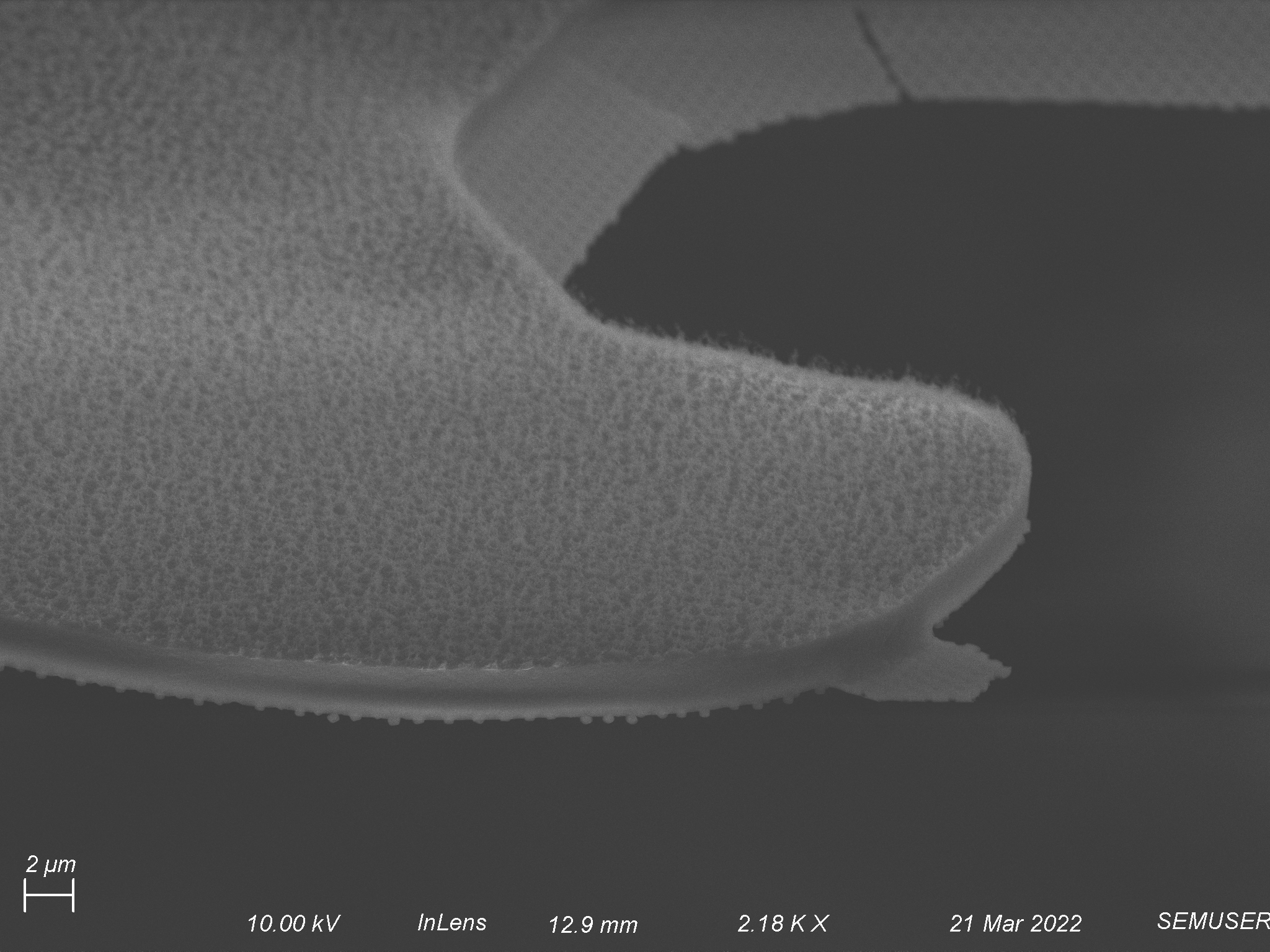
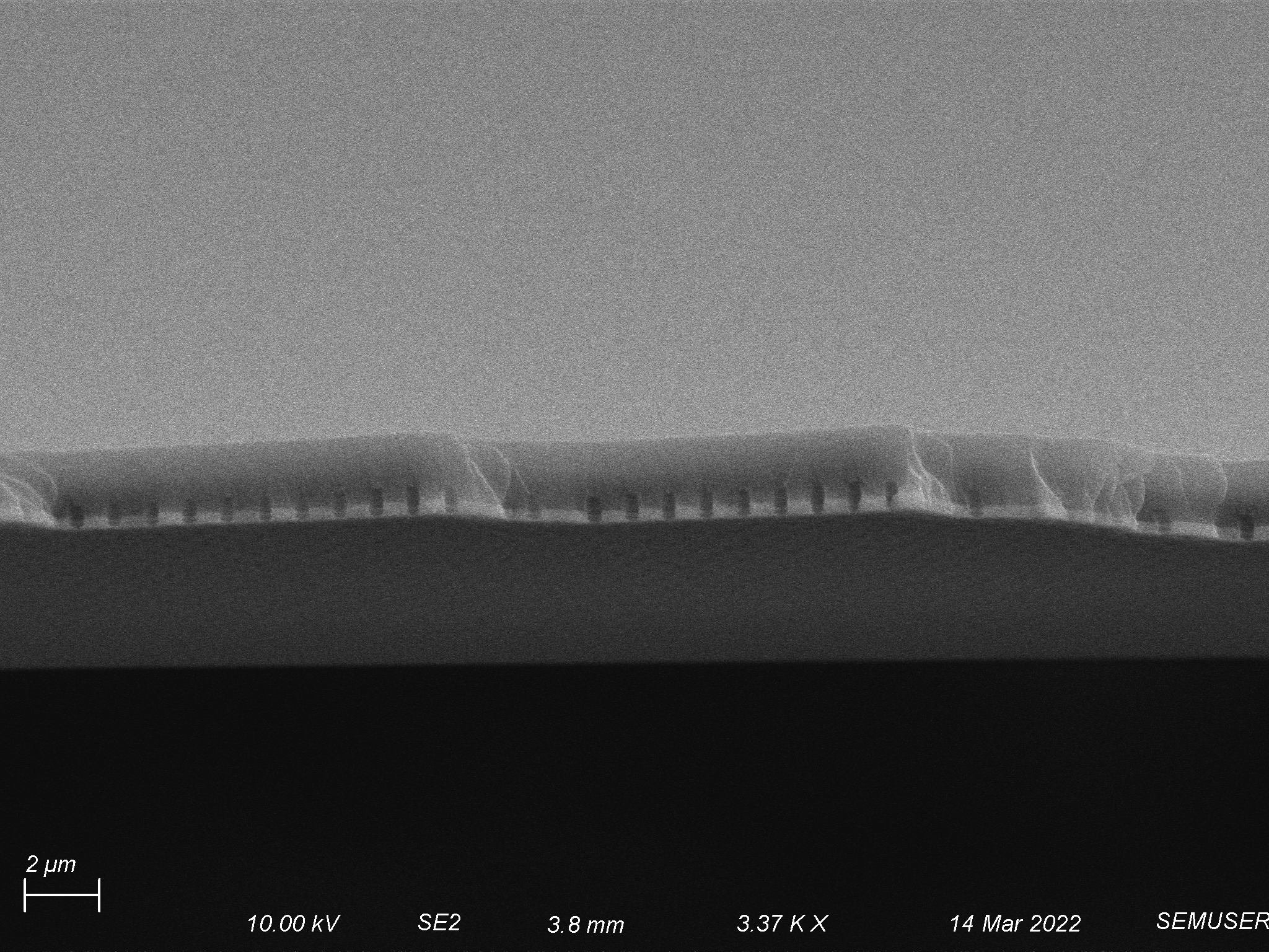
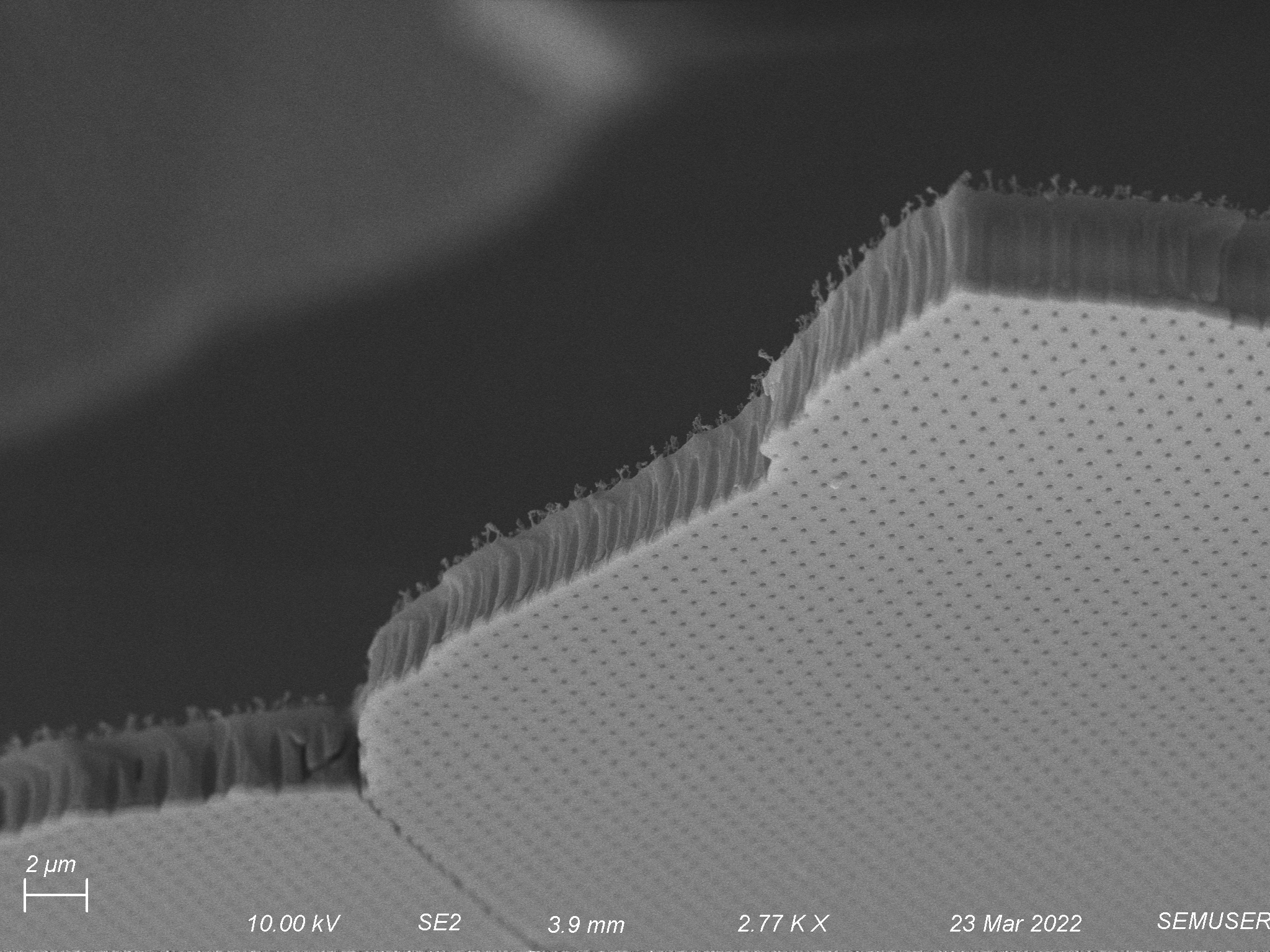
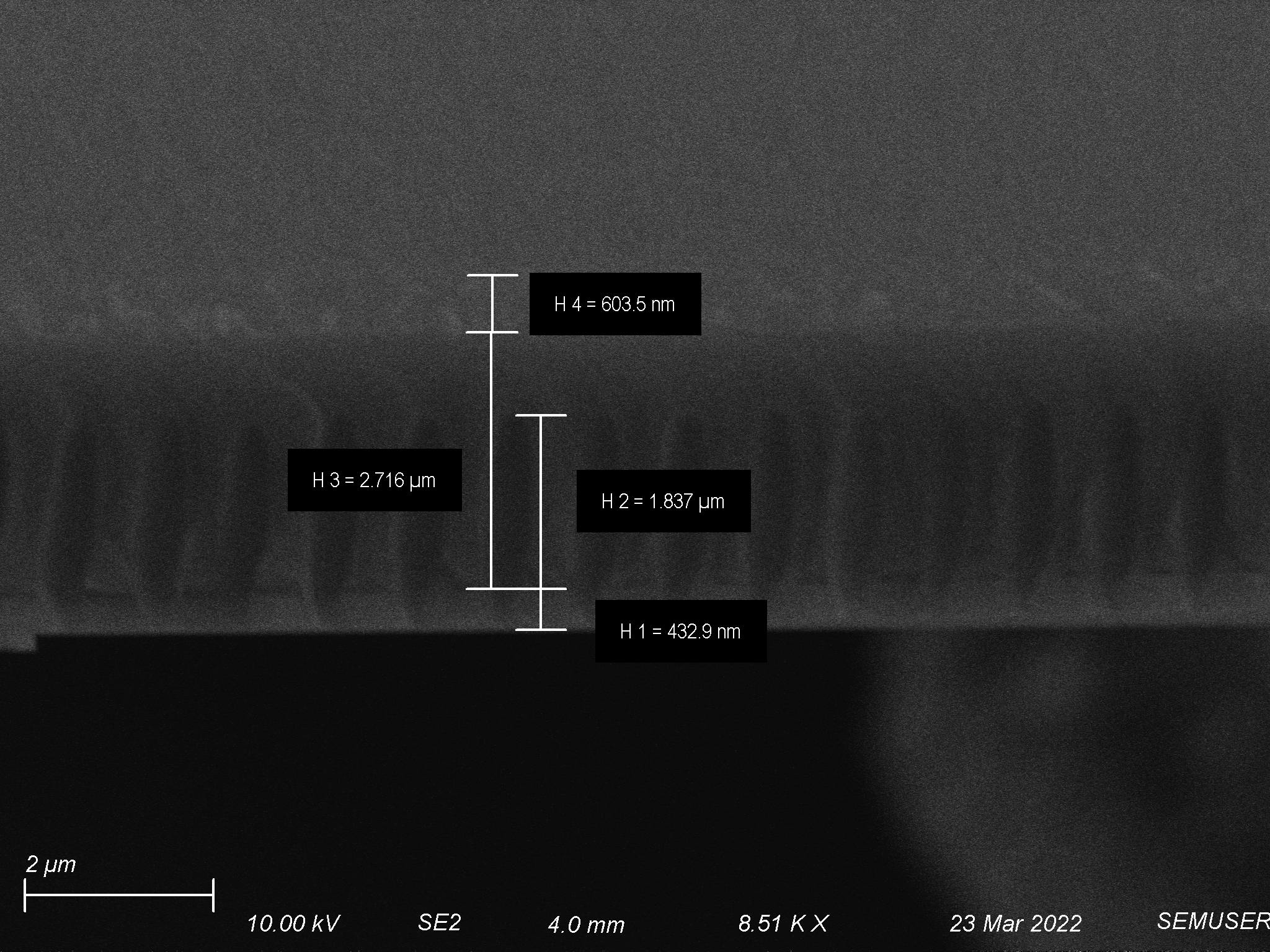
O2/Ar-12.5/12.5 sccms etch at 100 W for 15 minutes (on the back side of FSE-7)
Seeing how much polymer was taken away using 150 W of power, I tried to use less power this time to make the process more controlled and to decrease the horizontal blow out that we saw in the polymer tunnels. Anticipating the polymer thickness to be closer to 1 um, I extended the etch time by only 5 minutes to account for the change in power. Unfortunately, the polymer was about twice as thick as I had anticipated, so we ultimately did not end up getting completely through it. This resulted in the formation of interesting looking polymer pillars. Fortunately, we did see a decrease in the amount of horizontal blow out within the tunnels which made me believe that this was a good recipe to use moving forward with a polymer that is closer to 1 um in thickness.
Pore Morphology

Depth

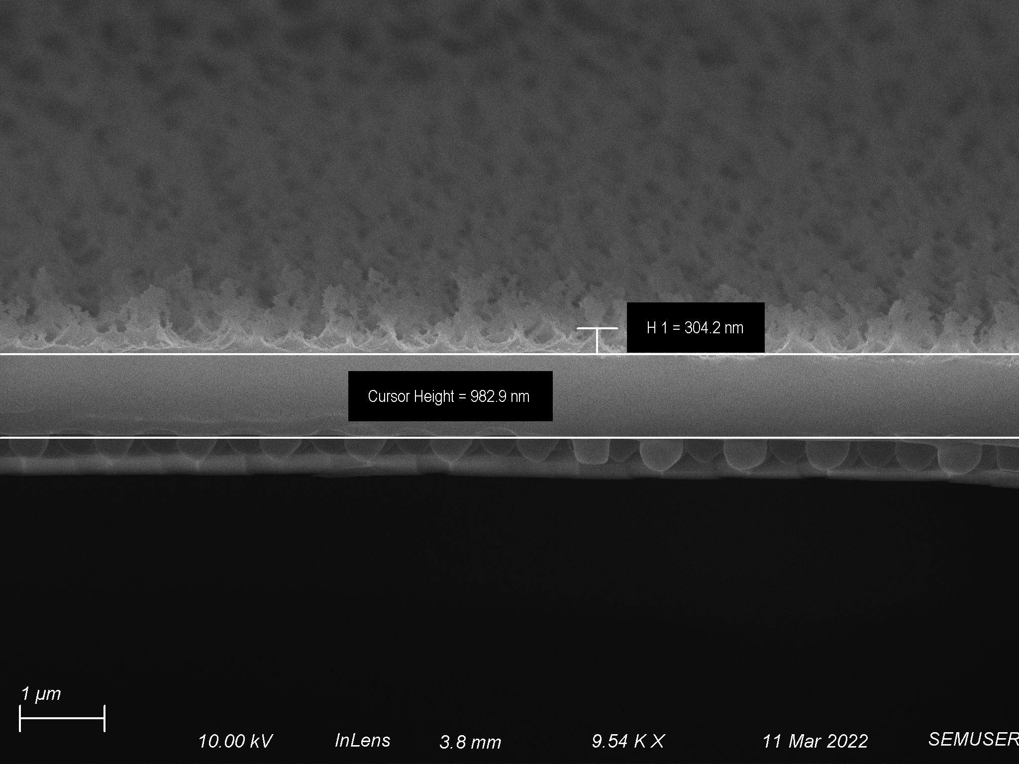
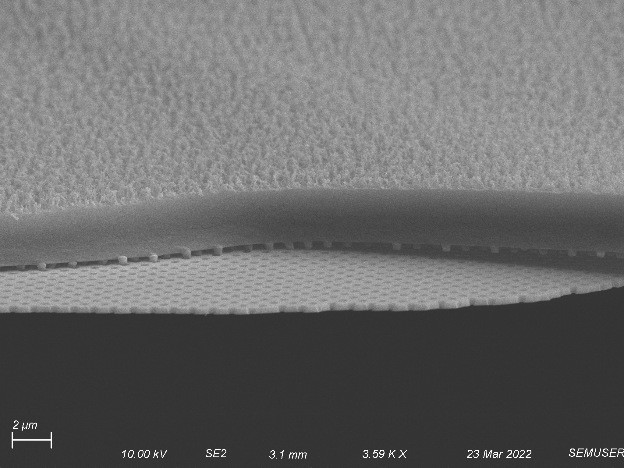
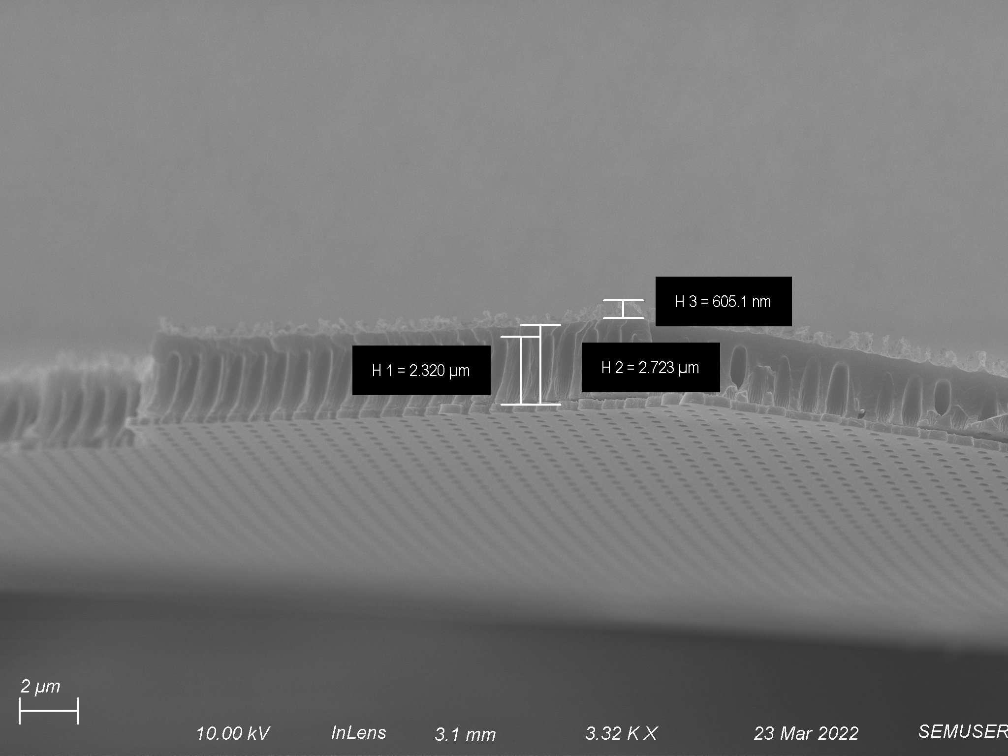
O2/Ar-12.5/12.5 sccms etch at 100 W for 20 minutes (on the back side of FSE-3b)
The goal with this back etch was to not only get completely through the polymer, but to also thin down the size of the polymer overall. Based off of our result the first time I tried this etch, I was expecting a 1.7 um thick polymer with a smooth surface. Based off of this I extended the etch time slightly to ensure that I made it through the polymer and hopefully thinned the polymer down to 1 um. Unfortunately, as mentioned in this particular flat side etch, the polymer was not as thin as I thought it was and I was only able to make it about three quarters of the way through. Despite this, I was encouraged by the pore fidelity.
Pore Morphology
Depth
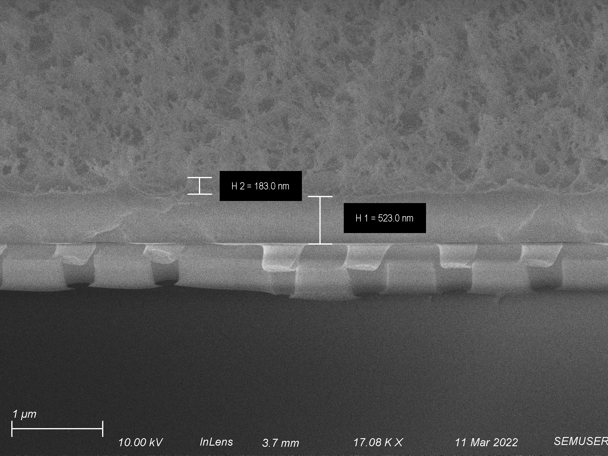
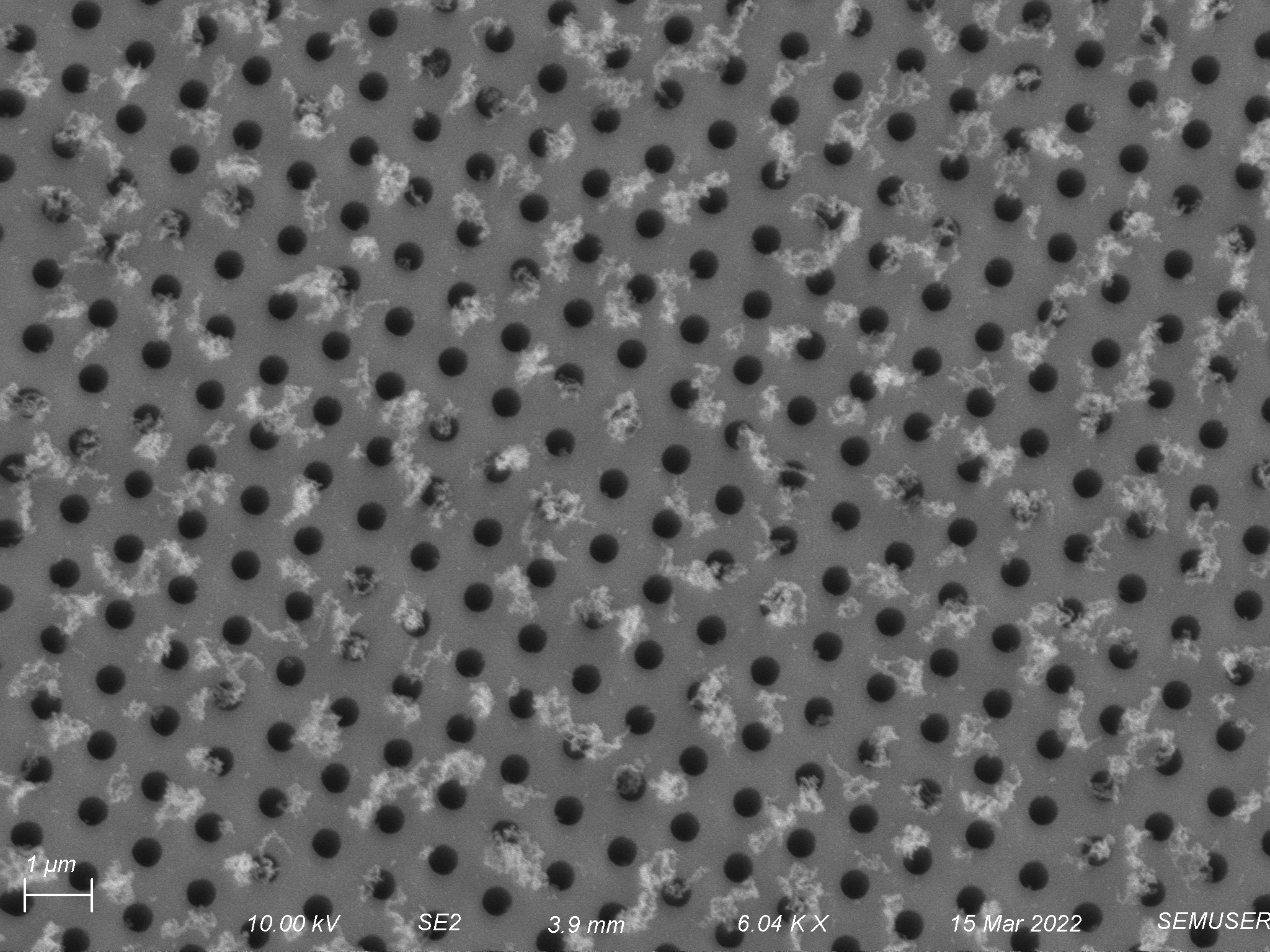
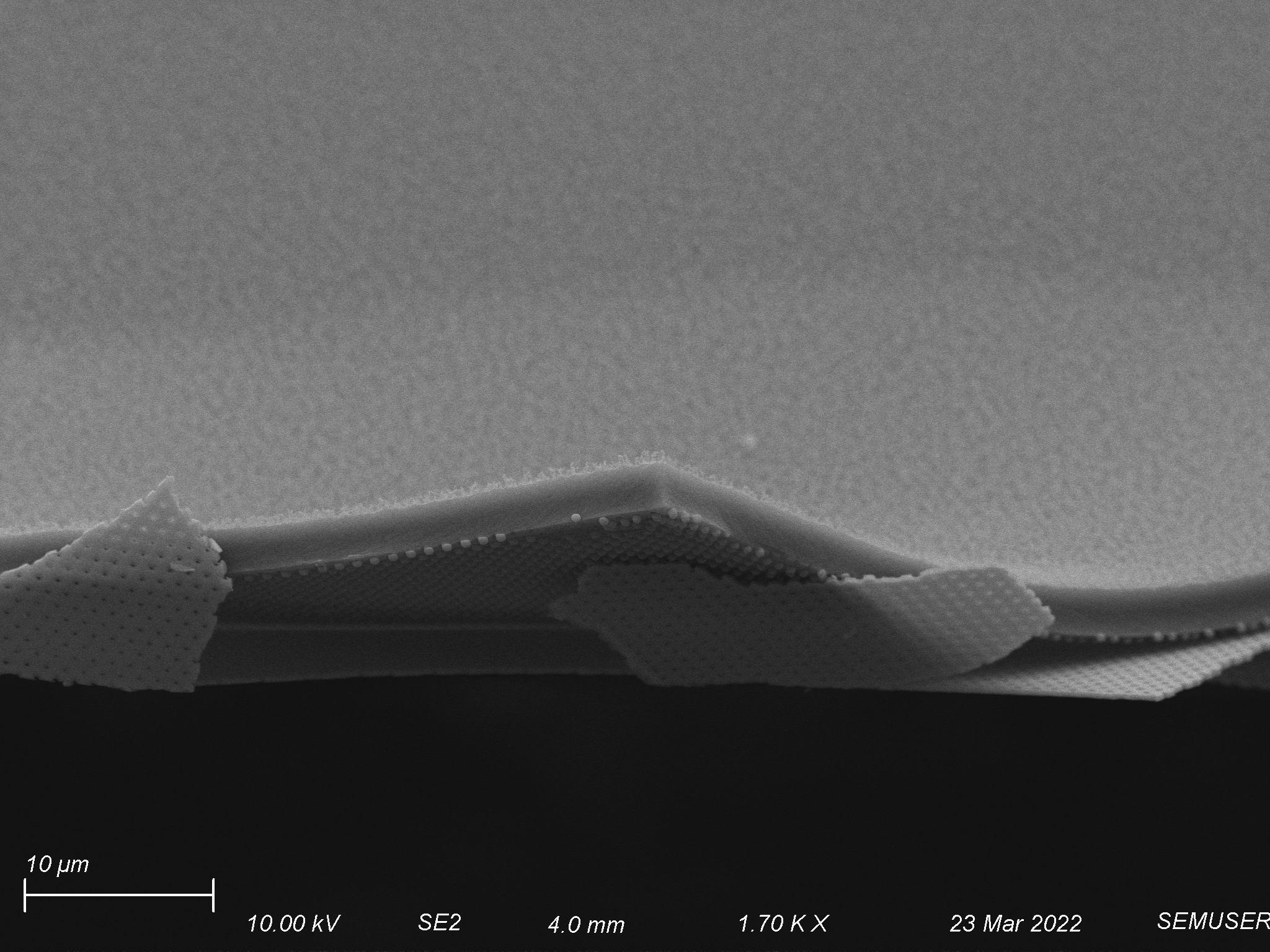
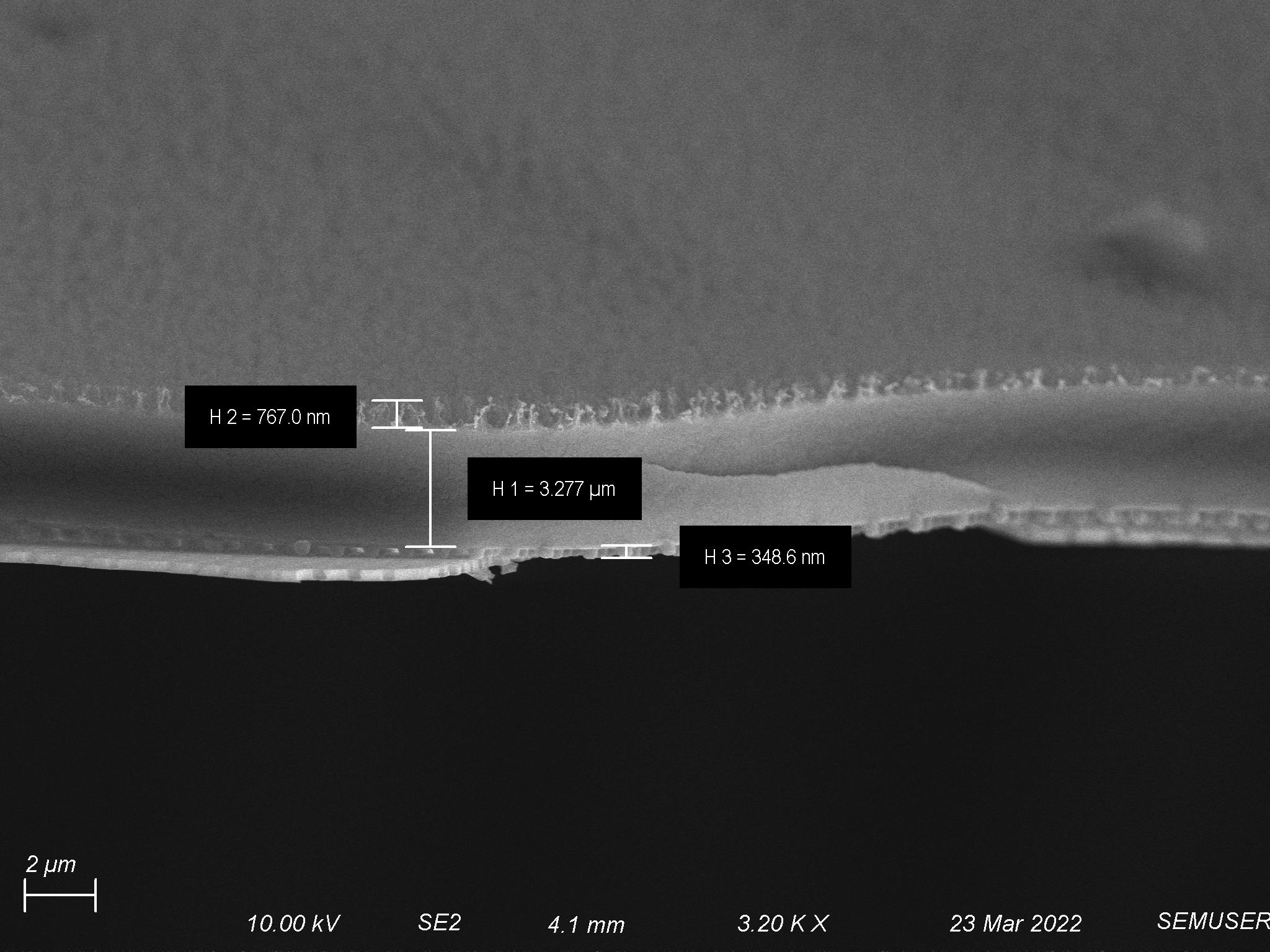
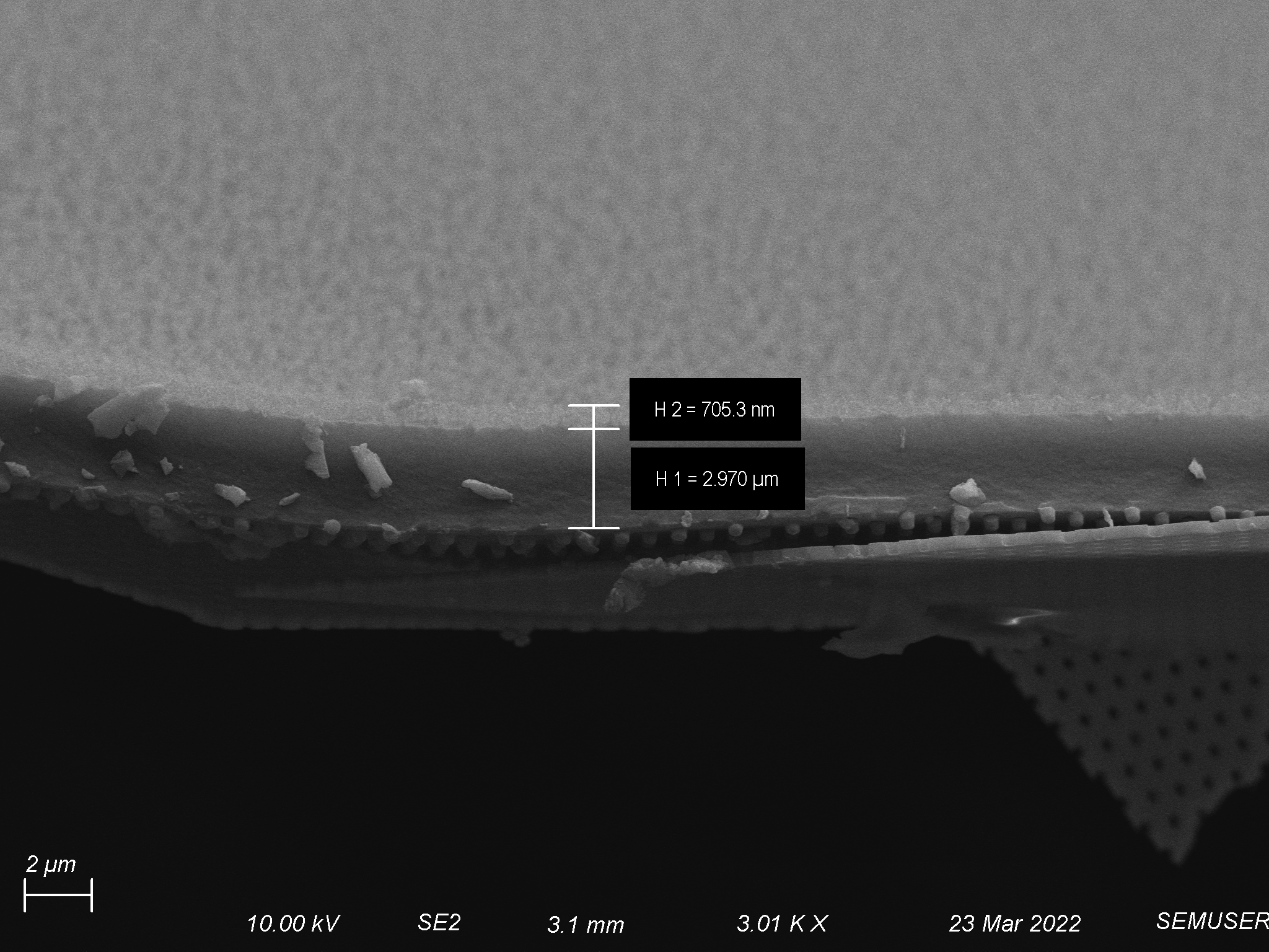
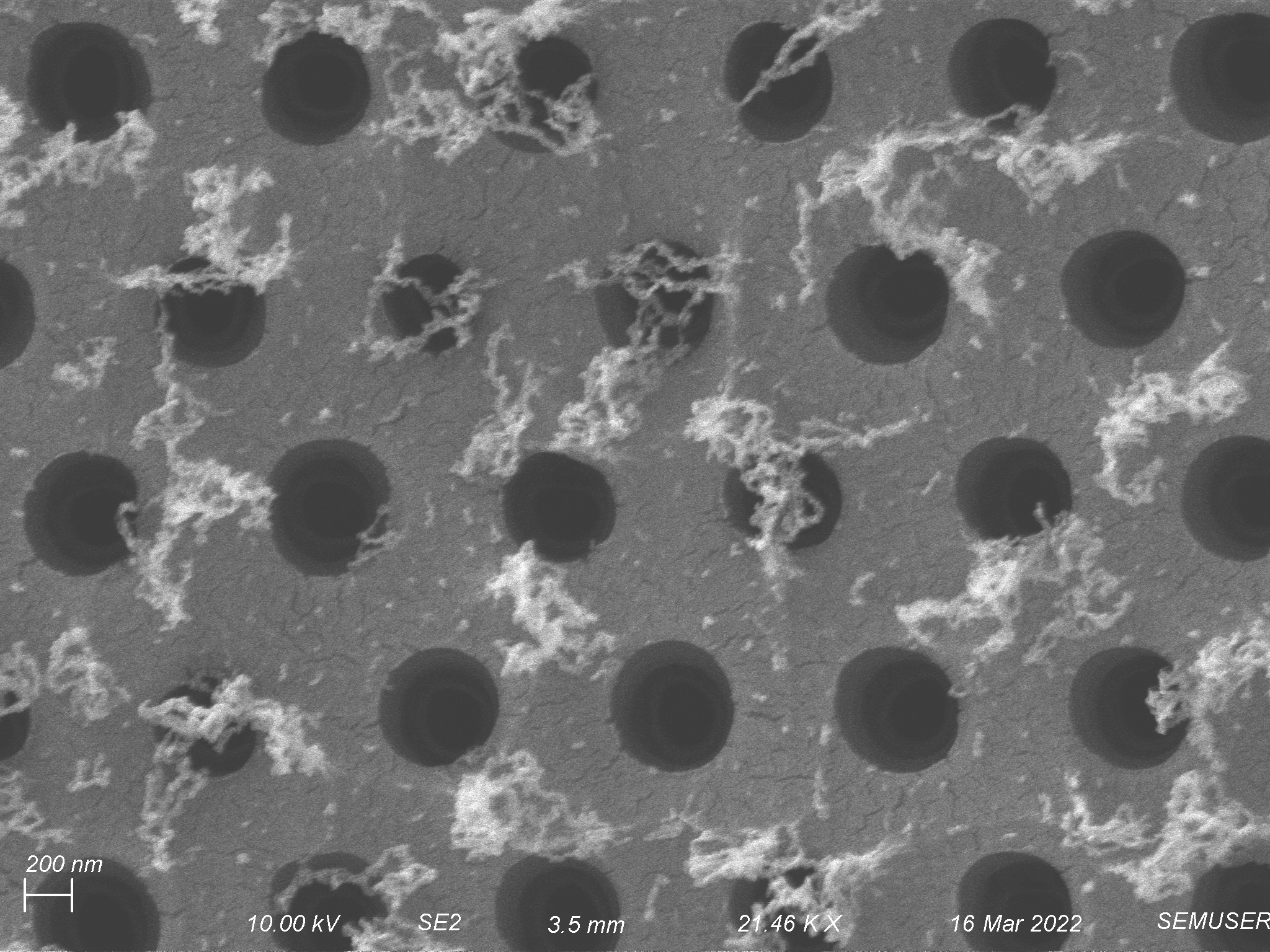
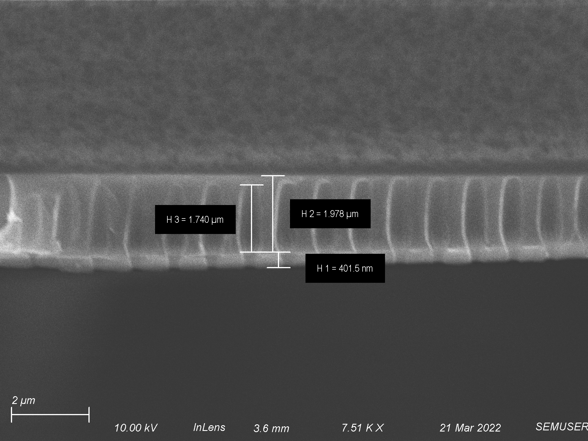
O2/Ar-12.5/12.5 sccms etch at 100 W for 15 minutes Round 2 (on the back side of FSE-2b)
If everything had gone according to plan, this back etch was just going to be used to clean up some surface roughness left over from the flat side etch. Unfortunately as was shown and discussed in the flat etch side of this experiment, the polymer was thicker than it was supposed to be. Because of this we did not make it through the polymer layer in most areas, but because of the aforementioned variability in layer thickness within this particular coating we did barely make it through in other areas. Since a relatively low amount of reactive ion gasses and plasma made it to the flat side of the polymer, very little surface smoothing was observed. Despite working through a much thicker layer of polymer than anticipated, anisotropy seemed high and pore fidelity was good. At its widest the pore was blown out horizontally ~300 nm. I anticipate with a thinner polymer layer this will decrease as we shorten our etch length.
Pore Morphology

Depth

Identifying the Saboteur: PUA Itself
As more issues arose in my results, a reckoning became imminent. Luckily, the case was closed as quickly as it was opened up as a check of PUA thickness after deposition but before any etching revealed a discrepancy in performance. Where we used to reproducibly get 4 um layers of PUA, we were now getting almost 7 um thick PUA layers. This explains why the last three flat side etches I attempted produced layers no where near as thin as I expected them to.

Moving Forward
The biggest take away from this round of experiments was that we can combine the flat side etch and the back side etch to produce our target PUA thickness and surface morphology. Previously it seemed that our outcome solely relied on the flat side etch which may not have been able to produce on its own. We seem very close to having an ideal flat side etch and we also have a back side etch which seems to be working very well. Separately, we learned that PUA has a shelf life which we must be conscientious of. With new PUA in hand, our next set of experiments should get us even closer, if not to all the way to our final product.