CytoVu Static TEER Device with Yuchen Wang
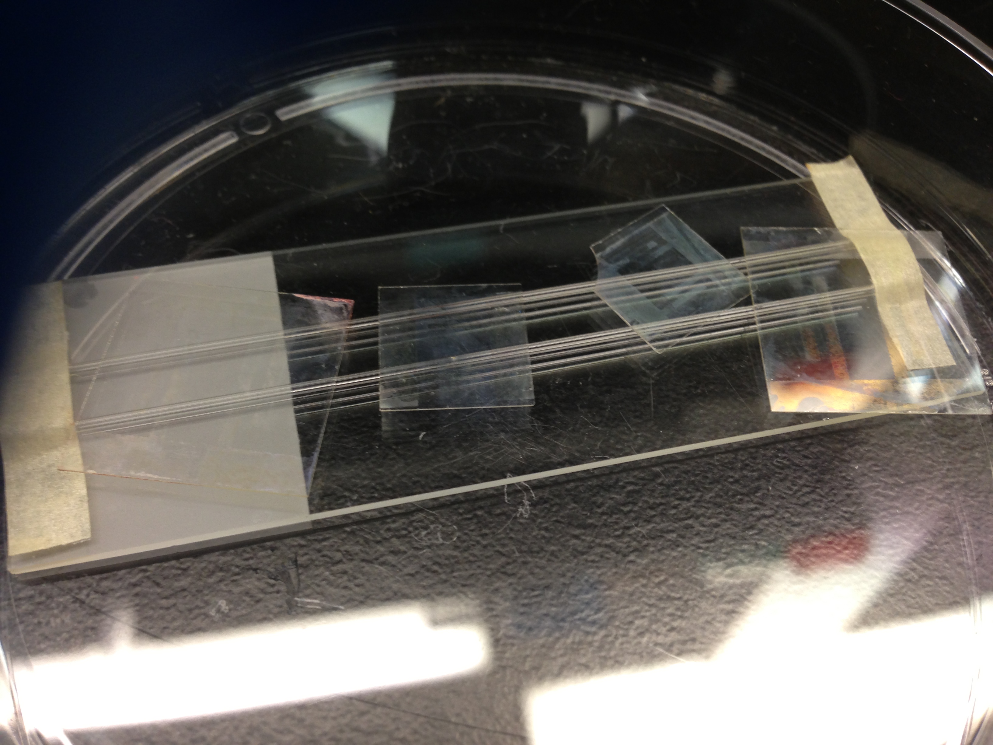
Yuchen and I have been tasked with integrating TEER electrodes into the Cytovu format. The general idea was to fabricate the TEER electrodes similarly to what I have done already, then add them to the current Cytovu device, using UV ozone bonding and PDMS (to cement in the top electrode). I drew some electrodes to that cover the 4 wells, but also show that we could address individual wells if we wanted to by breaking up the electrode pattern. With a higher quality mask/ more rigorous clean, the electrodes can have much higher quality and lower resistance. Also, an ITO shadow mask deposition is a possibility for the 18x18mm slide, but probably not for the 12x12mm slide addressing individual wells, due to the spacing of the electrodes being very small.
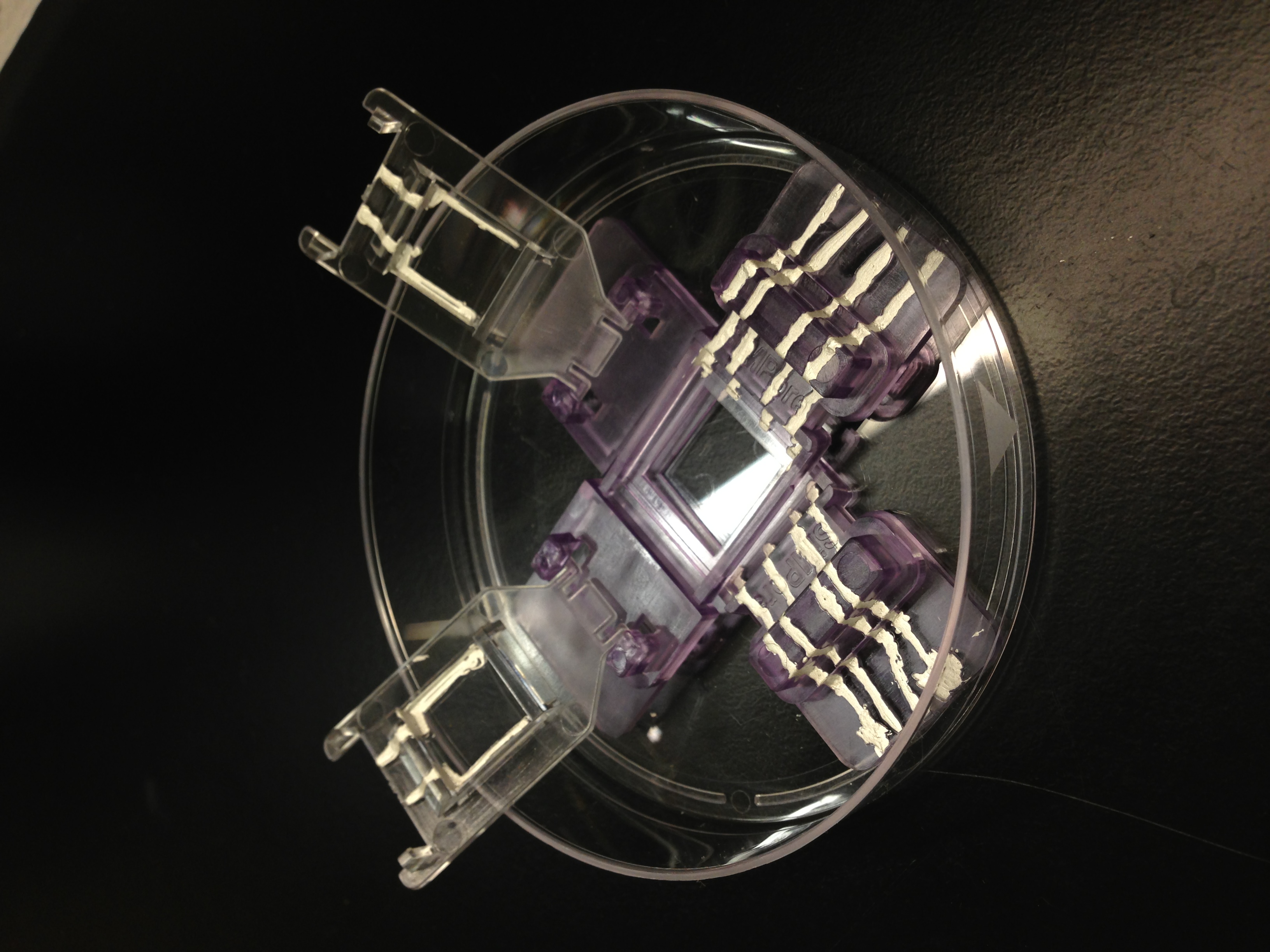
The lid is hinged and when the lid is closed, the conductive lines on the roof make contact with the lines on the base, leading out to a bus for access. 4 Lines for the 4 TEER electrodes.
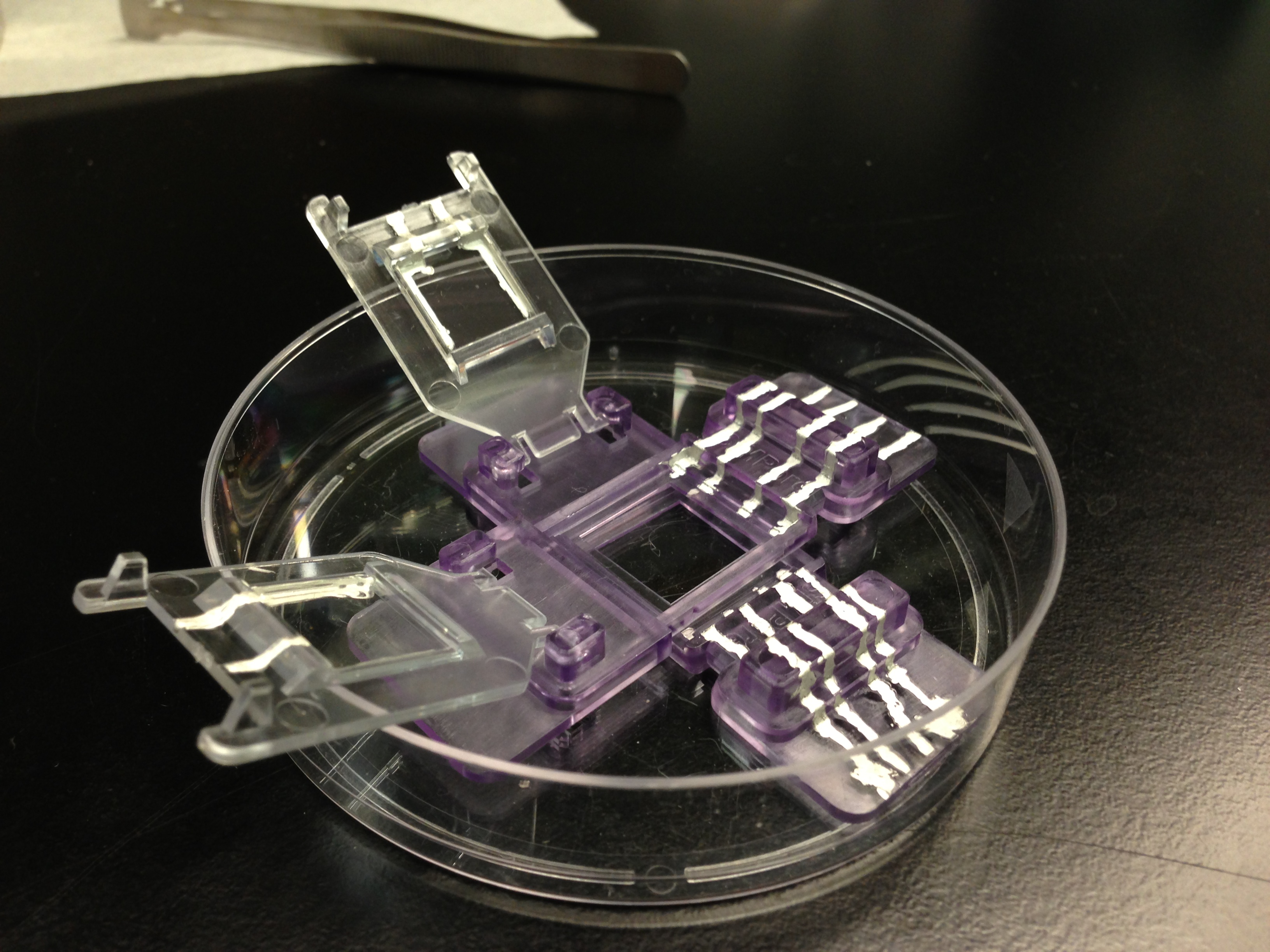
To add the Cytovu device into the holder, we simply placed the device in the well (after removing the mounting square) and joined the ITO pad to the conductive lines with more circuit writer ink. After curing in the oven for 1 hr, we tested the connection by measuring the resistance from the ITO pad to the bus line pad. The resistance was approximately that of the ITO pad alone, but was not verified vigorously.
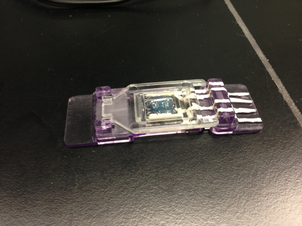
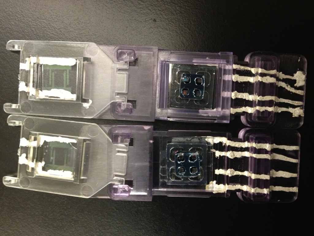
- Cytovu Top Down View Lid Open
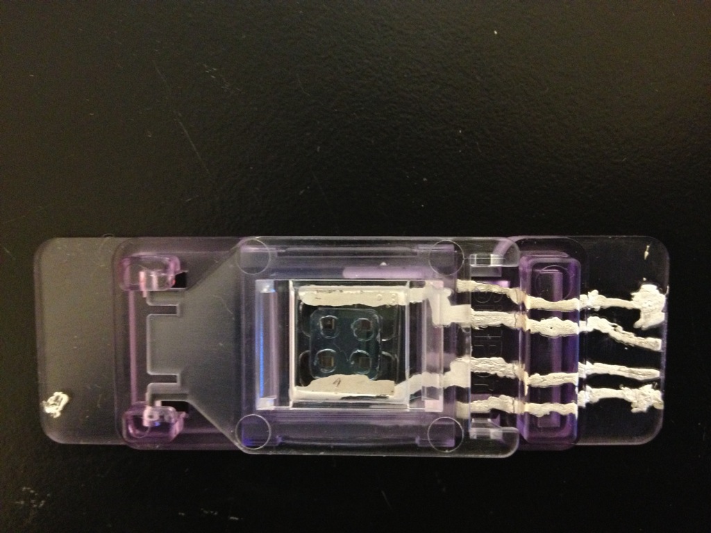
The next step is to add media and cells to see if they survive. If media somehow contacts the silver lines, it will probably kill the cells. I’m looking for an insulator that can be spread over the silver lines to prevent accidental contact. PDMS may be a candidate if the silver doesn’t diffuse easily through it, though I’m pretty sure there is a commercially available solution.
Fabrication Steps
Fabricate ITO Electrodes
- Deposit 2000 Angstroms, ITO, Room Temperature Using Kurt Lesker Sputterer (Use ITO 2000 Angstrom Recipe, takes about 2.5 hr, with cool down)
- Tape 18x18mm and 12x12mm coverslips onto platen with kapton tape. Use tape on the edge as thin as possible, to maximize the amount of area exposed to the sputter.
- Clean Slides with Alcohol, dry in oven
- Lithography
- Use the small sample holder on the spin coater. If the vacuum isn’t working properly, try adding a little teflon tape to the spin-coater base to make a seal (don’t occlude the vacuum port)
- Identify the conductive side with a multimeter/ohmmeter setup.
- Program the spin coater to do 5s-500rpm 45s-3500rpm
- Turn on the two hotplates, one at 110C and the other at 150C
- Program the timers (over 110C hotplate ->63 seconds, over 150C hotplate ->200 seconds)
- Turn on the Mask aligner lamp, needs to warm up for about 25 minutes. Turn on the vacuum by opening the valve on the wall.
- Place the sample with the conductive side up onto the spin-chuck, apply vacuum. Make sure its as well centered as possible.
- Start spin-coater
- While in the low rpm step, apply a drop or two of HMDS
- When the spin-coater finishes, place sample onto 110C hotplate (always conductive side up), start the timer
- Before the timer ends, hit the stop button to keep the alarm from sounding.
- Place the sample onto the spin-coater and start it. This time, apply a few drops of photoresist to the surface
- Prebake the sample, 110C for 60 seconds
- Place sample and mask onto contact aligner chuck (photoresist side up), use substrate vacuum to suck the transparency down into contact with the surface
- Set expose time to 5 seconds
- Drag the stage into the mask aligner. The aligner will expose automatically.
- Remove sample, place onto 110C hotplate for 60 seconds
- Place sample onto spin coater, activate vacuum. Puddle develop for 45 seconds by dropping enough developer onto the surface to cover the entire surface.
- Be careful not to add too much; it can get sucked into the vacuum port, or leak all over the coater
- Start the spin coater but let it only run for a few seconds at high rpm to drive off the developer
- Stop the spin coater
- Start vacuum again, puddle develop for 45 seconds again.
- Start the spin coater. While it is running, spray DI water for 20 seconds onto surface to stop development.
- Place sample onto 150C hotplate for 200 seconds to stabilize and hardbake photoresist pattern
- Etching
- Use 12M HCl to etch Photoresist coated slides for 45 seconds
- Rinse in DI water
- Dry using oven or kim wipe
- Strip photoresist with acetone, 30 seconds
- Rinse in DI water
- Dry using oven or kim wipe
RTP pnc-Si filters
- Place susceptor and lid gently into RTP tool
- Run warm up recipe on the RTP
- Wait for the Oven to cool below 300 C
- Remove susceptor and lid, take off lid
- Place samples in susceptor, flat side up (blue), cover with lid
- Place susceptor and lid gently into the RTP tool
- Use the Simpore Post anneal recipe
- Wait for the Oven to cool below 300 C
- Remove Susceptor, take off lid
- Remove samples, place lid back on susceptor
- Wait for the oven to cool down to room temperature, then turn off tool
Modify Cytovu Base and Holder
- Prepare a 10:1 PDMS to Curing Agent mixture (2g is plenty)
- Outgas for 20 minutes in vacuum can
- Take individual Cytovu lid and coat inner surface with PDMS.
- Use a pipette tip to deposit a nice bead in the center of the window.
- Embed 12×12 electrode into lid
- Try to reduce air bubbles by placing one side down first and gradually spread the pdms out with the other side.
- Cure in the 70C oven for 1 hour
- Use circuit writer ink to draw electrode pattern on base.
- Remove mounting square from base
- Press the pen tip against a surface and squeeze the barrel to get conductive liquid to come out
- Make a large bead for the contact pads that will interface with the roof
- Cure in the ambient oven for 1 hour
- Check electrical connections using multimeter (looking for shorts)
- It is likely that there will be some broken connections, repeat steps 5-6 until there are no shorts.
- Once the lid is finished curing, draw electrode pattern on the roof.
- Connect the ITO contact pad to the edge of the lid with ink
- Build up a bump on the contact pad where it will interface with the base
- Cure in the ambient oven for 1 hour
- Check electrical connections using multimeter. Measure from the ITO pad to the edge of the lid; you should see a 1-10 kohm resistance.
- Repeat steps 10-11 until there are no shorts
- Verify the contact pad short by closing the lid on the base, measuring the lines through the opening in the base through to the lid and then out to the bus bar
Assemble Cytovu
- Use UV ozone bonding to assemble the cytovu device layer by layer. I find 15 minutes of exposure time works best. Chain them one after another.
- Large gasket::18x18mm electrode
- pnc-si Filter::Large gasket/18x18mm electrode stack
- Place the flat side into contact with the large gasket
- Small gasket::pnc-si Filter/Large gasket/18x18mm electrode stack
- Cure on hotplate, 150C, 30 minutes
- Sterilize in autoclave, cycle 4
Install Cytovu into Base
- Place Cytovu into base with the glass side on the bottom, as planar as possible
- Use conductive ink to join ITO pad on the cytovu to the bus bar on the base
- Cure for 1 hr in the ambient 70C oven
- Verify the connection with a multimeter, from the ITO pad to the end of the bus bar.
- Repeat 2-4 if there are open circuits.
- Gently replace mounting square, solidifying the Cytovu to the base.
Probable Usage (Yuchen)
Protocol of seeding cells on CytoVu:
- Pre-condition the membrane by applying media (10% FBS), 25 μl to the basal wells and 10 μl to apical wells.
- Replace lid and incubate at least 2 hours.
- Aspirate media using hand-held pipettes.
- Add 10 μl of suspended cells to apical well.
- Add 25 μl of media in basal well.
- Replace lid and allow cells to attach to membrane. Incubate for approx. 2 hours.
- Replace new media to remove excess cells in apical wells.
- Incubate to let cells grow to reach confluence. Change media every day.