The overall goal was to see is if it was possible to create a reliable low resolution mask that can be used for crosslinking PEG structures using a laser printer and transparencies sheets. With these masks, I explored to see if there is an effect on the PEG structures when dimensions such as the spacings between PEG structures and height are changed.
The printer’s limit must be defined for vertical, horizontal, and grid masks. For reference, clear/white is PEG structure and black is empty channel/window.
First, two different applications (Adobe Reader and Preview) were compared to see if there are any differences. Both pictures below are 50um lines (clear) with 100um spaces (black). The one on the top was printed using the view Adobe Reader while the one on the bottom was with Preview with document setting of high resolution.

L: Printed with Adobe Reader (10x); R: Printed with Preview (10x)
A few masks were created where it was drawn with black rectangles/squares for the spacing and no white rectangles. The black rectangles/squares were arranged accordingly. In the pictures shown below, the printer consistently printed clear lines when white on black was drawn in Illustrator. For black rectangles/squares only, the printer was only able to print a few faint lines. As the spacing grows larger for both lines and grids, the faint lines disappear and essentially a black sheet is printed. For an optimal mask, it must be made with white rectangles on top of a black background. The white rectangles are arranged accordingly for channels or grids.
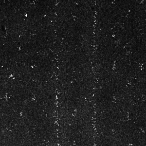
L: 50/100-white rectangles on black background (10x); R: 50/100-black rectangles only (10x)

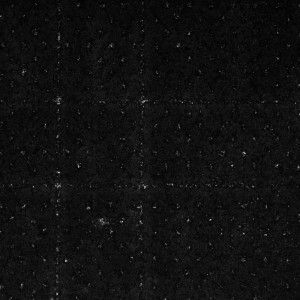
L: 50/750-white rectangles on black background (4x); R: 50/750-black squares only (4x)
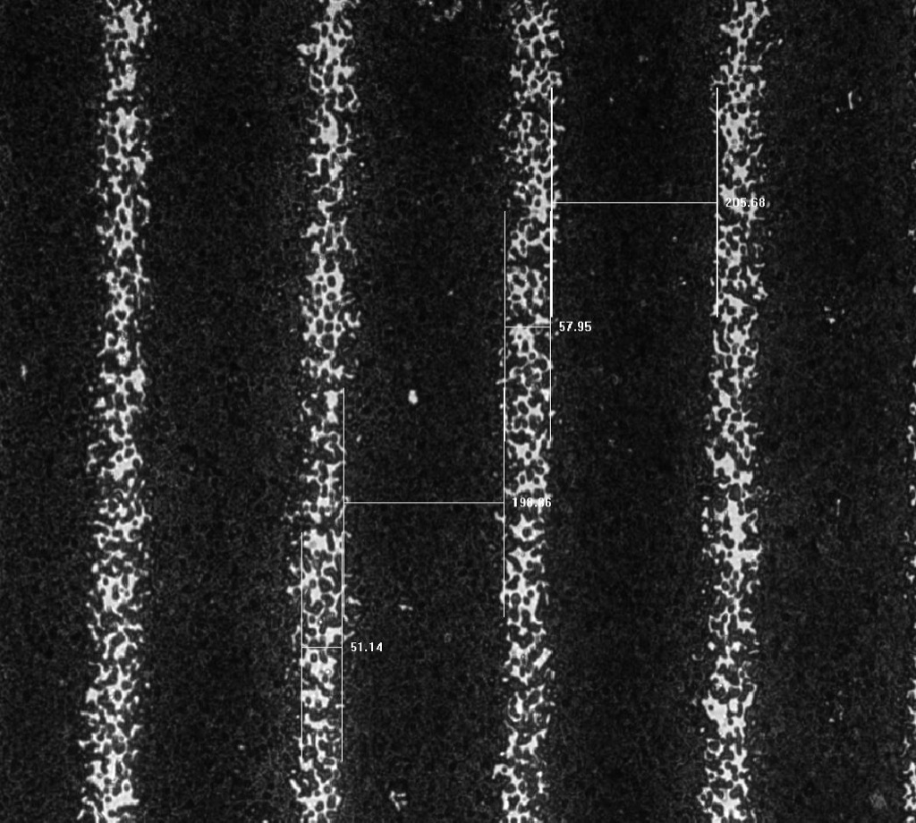
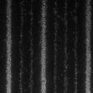
For bars, the thinnest white (PEG structure) that the printer can print consistently is 50 um. The thinnest black (spacing) is 200 um (shown below).

For the grid masks, the smallest white lines was 50 um but it could only be done with 750 x 750 um windows (shown below) or larger. A table below shows all the grids that are acceptable for use.
|
White-PEG structures (um)
|
Black-Windows (um)
|
|
50
|
750+
|
|
100
|
500/750+
|
|
200
|
250/500/750+
|
|
500
|
250/500/750+
|
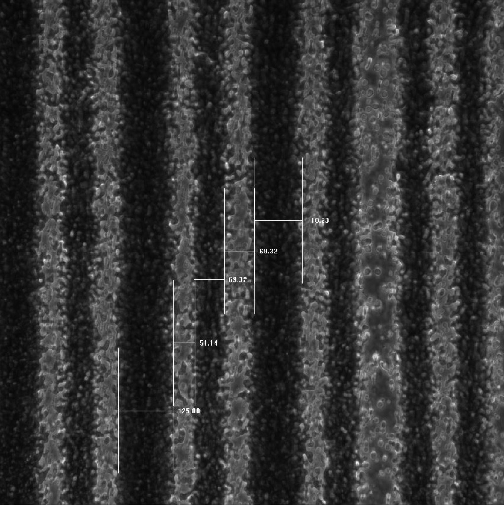
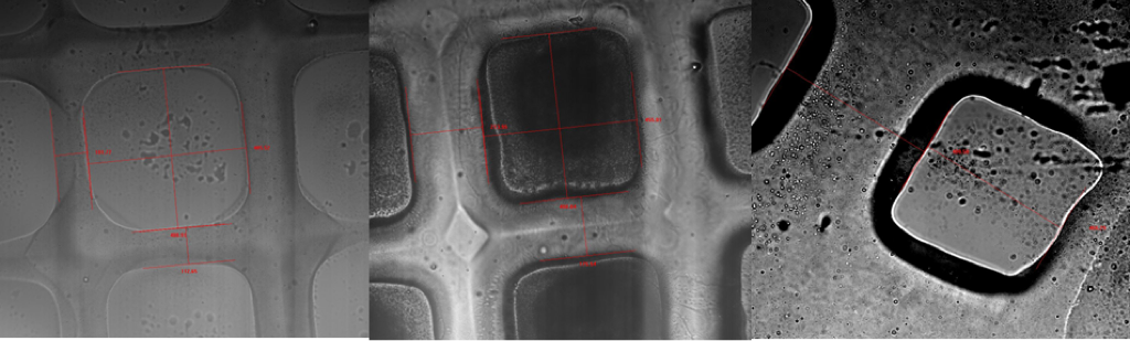
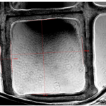
A 300 um gasket was used to control the height of the PEG structures. PEG structures were crosslinked onto cover slips with various sizes to see if the size would stay consistent throughout the 300 um height. 50 um, 200 um and 500 um wide PEG lines were looked at. All of PEG structures have 250 um spacings/channels. Due to the PEG structures being transparent, it was difficult to focus on the top to see what the width was but if you focus on the bottom, an outline can be see of the top. The top level is consistently smaller than the bottom which means the PEG structure does not have a vertical 90 degree side but instead tapers. I am assuming it is due to the scattering effect when the UV light transmit through the glass and then through the PBS/PEG/crosslinker solution. 300 um gasket is too tall for the 50 um PEG structure. It seems to go to a point at the top.
L:50/250 (4x); C: 200/250 (10x); R: 500/250 (10x)
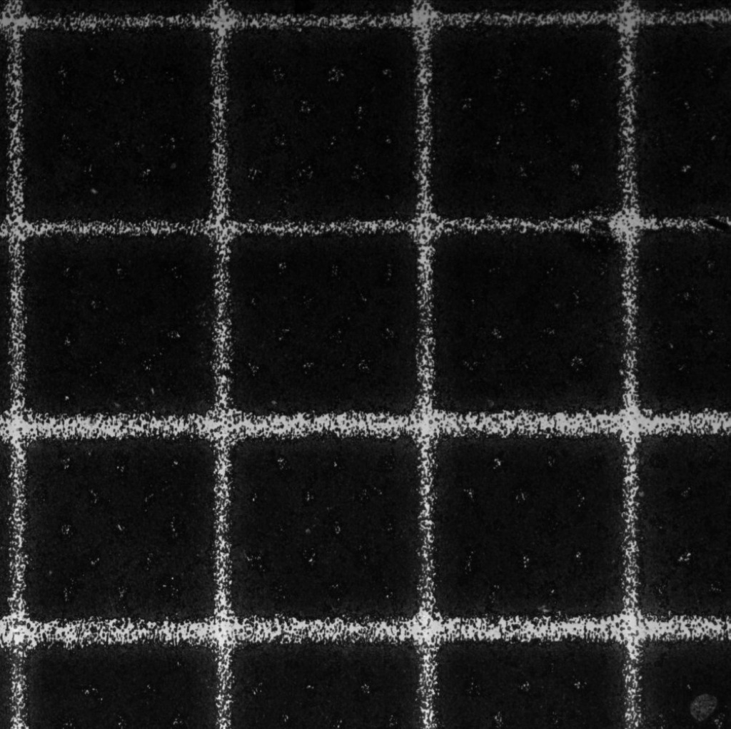
Along with line PEG structures, grid PEG structures were crosslinked to glass coverslips. To keep the setup the same as the lines, a 300 um gasket was used to control the height. The grid’s width was the same as the lines where it changes width with respect to the z-axis.
L:100/500 (10x); C:200/500 (10x); R: 500/500 (10x)
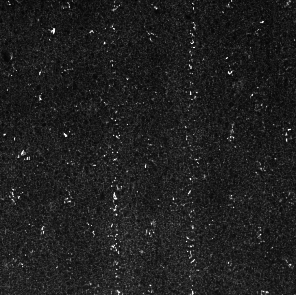
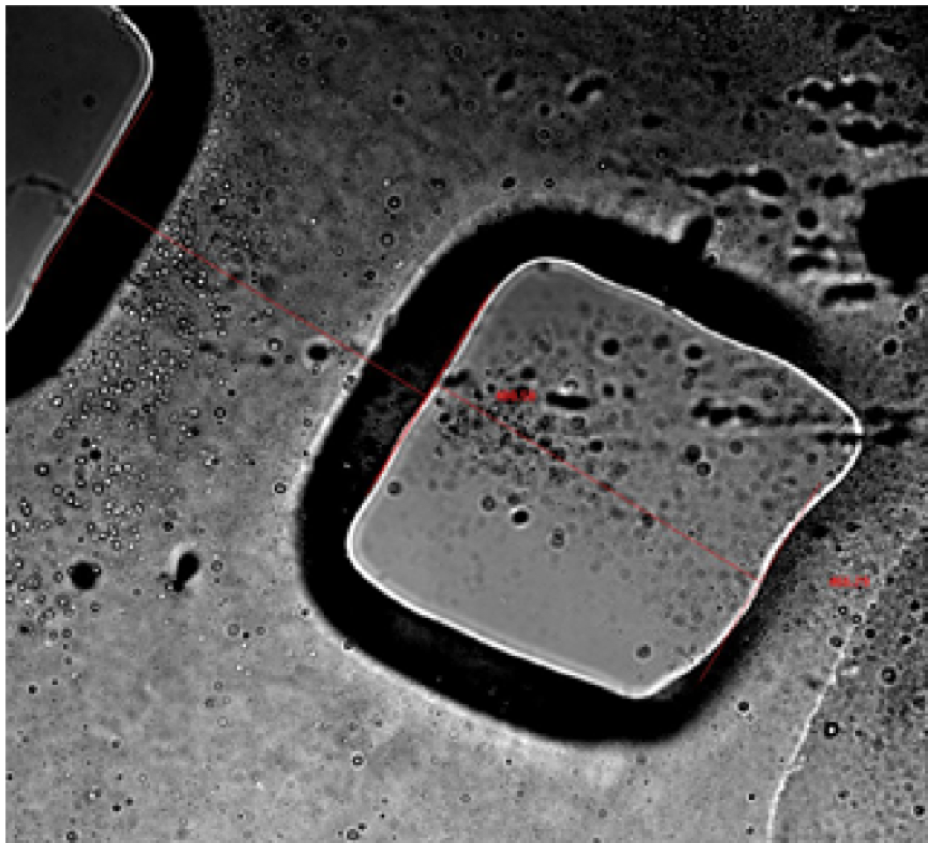
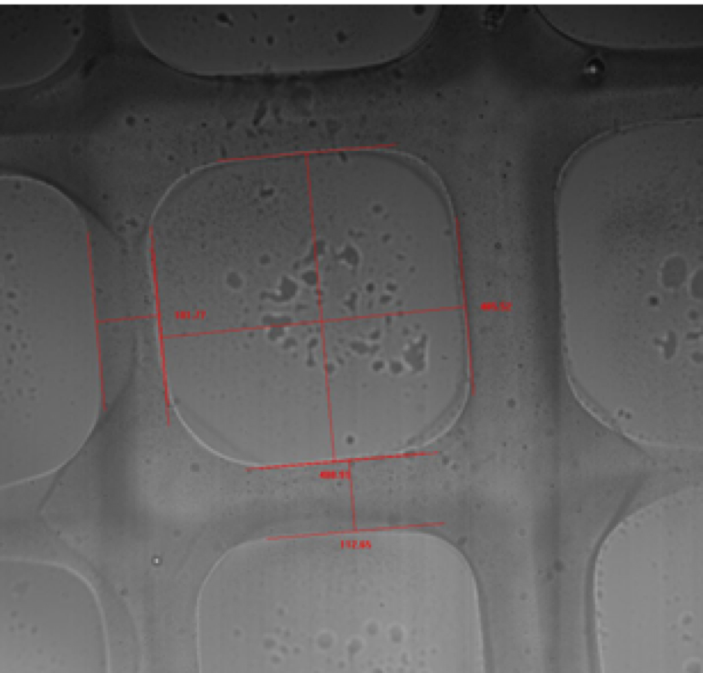
Next, the effect of the spacing between PEG structures was looked at. The major difference between the PEG structures when the spacing changed from 250 um to 500 um was the exposure. The PEG structures seem to form better when it is spaced closer together than when further apart. The PEG structure has a smaller top surface with the 500 um spacing than with the 250 um spacing. The grids showed the same effect as lines. The PEG structures form better when the windows are smaller. It may be due to scattering effect of the UV light.
L:50/250 (4x); C: 200/250 (10x); R: 500/250 (10x)
L:50/500 (4x); C: 200/500 (10x); R: 500/500 (10x)

L:100/500 (10x); R: 100/750 (10x)
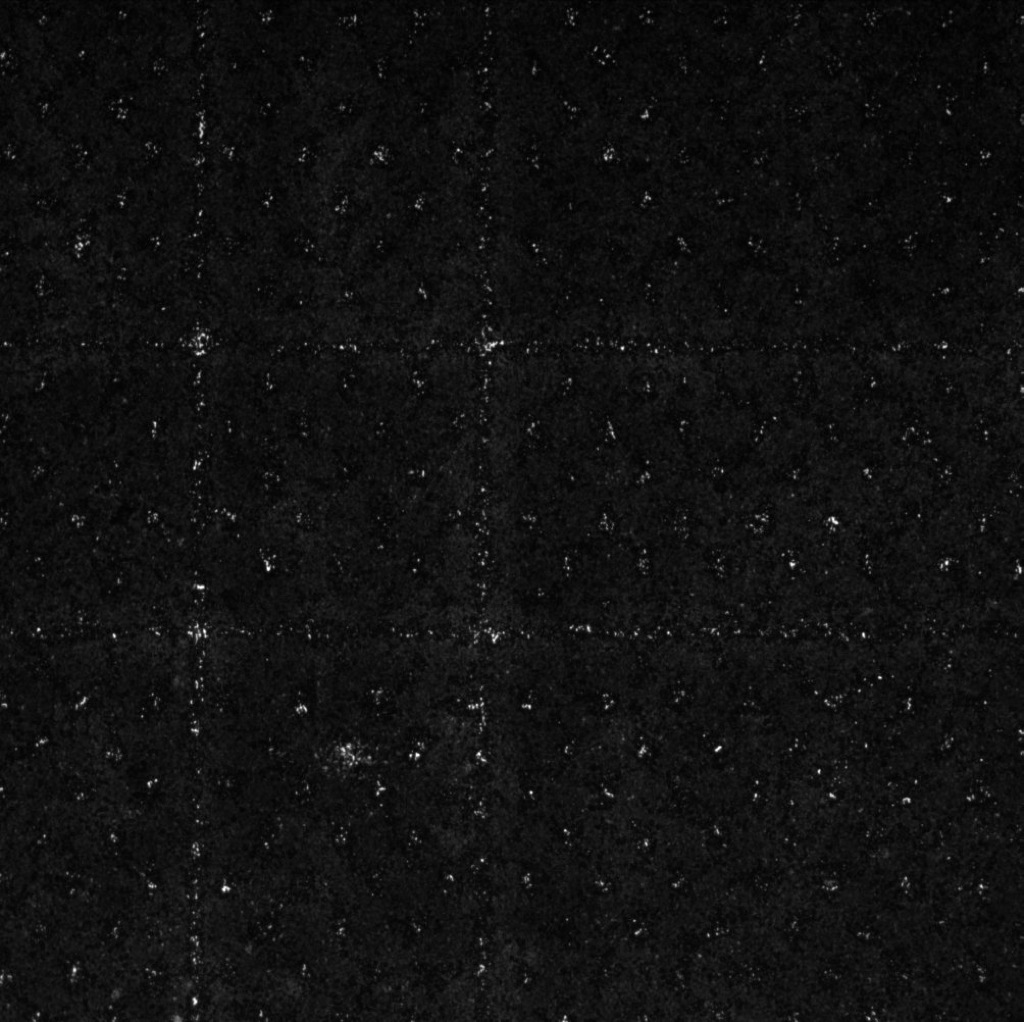
Lastly, PEG structures were created with minimal height by placing the solution between two glass cover slips. For some reason, when I tried to crosslink line PEG structures, either it will not crosslink or a film would crosslink to the entire glass. I was only able to crosslink grid structures.
R: 500/500 2 glasses (4x); L:250/750 2 glasses (4x)