Rotation Project: The Influence of Collagen Gels and Nanoporous Chips on Shear Based Endothelial Cell Alignment
As an introduction, my name is Alec Salminen. I received my BS in Biomedical Engineering at the University of Arkansas and am currently in my first year of the BME PhD program at the University of Rochester. As my rotation in the McGrath lab gets underway, I would like to share with the group my plans for the coming weeks.

When concerning the two subjects stated in the above figure (“Shear induced alignment of endothelial cells” and “Effects of substrate stiffness on endothelial cells”), endothelial cells are fairly well characterized in literature. A PubMed based search revealed that endothelial cell mechanobiology, in some form or another, has been an area of interest for many years. The gap that remains, however, is what lies in the middle of the diagram. The following post will address the preliminary data that inspired the lab to pursue this gap, as well as a quick interpretation of some published results.
Published Results
The PubMed search for studies/reviews relating to endothelial alignment and/or endothelial cell interaction with its ECM resulted in a large list of articles. However, only one paper found (Kohn et al., 2015) specifically addressed the two subjects in a manner that suited our interest. Using a cone-and-plate viscometer set-up, Kohn et al., 2015 subjected bovine aortic endothelial cells cultured on polyacrylamide (PA) gels to 12 dyn/cm^2 of fluid shear stress over a 24 hour period. They concluded in their results section that substrate stiffness does not affect shear based endothelial cell alignment (Figure 1A, 1B). They did find, however, that substrate stiffness does have a significant effect on cell perimeter and axis ratio (Figure 1C, 1D).
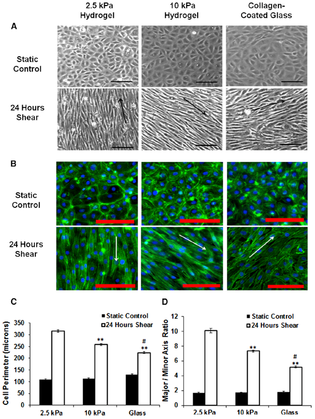
The results presented by Kohn et al., 2015 suggest that shear stress and endothelial interaction with their ECM to align are relatively independent of each other in this set-up. The set-up used in the McGrath lab, however, varies in many ways to the set-up used in this paper. For example, Kohn et al., 2015 uses the cone-and-plate viscometer to induce fluid shear while the McGrath lab uses a pump and microfluidic device. Another key difference is the materials on which the endothelial cells are seeded: Kohn et al., 2015 seeds cells on PA gels with a glass coverslip backing, while the McGrath group seeds their cells on a nanoporous chip with or without collagen gel added (further explanation in the preliminary data section). The nanoporous chip backing allows for greater diffusion through the cell layer as well as allows for a minor degree of flexibility that may influence cell behavior. In conclusion, this paper is highly relevant to the subject at hand, but the device set-up I plan to use will introduce some novel characteristics to the experiment that may lead to interesting results.
Preliminary Data
Note: All preliminary experiments were performed by Tejas Khire.
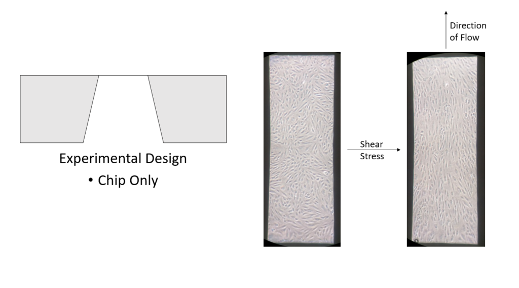
In order to observe HUVEC behavior on the nanoporous chip alone, cells were seeded and cultured directly on the chip. HUVECs were than subjected to 10 dyn/cm^2 flow for 24 hours. As expected, the endothelial cells aligned in the direction of flow over the 24 hour period (Figure 2).
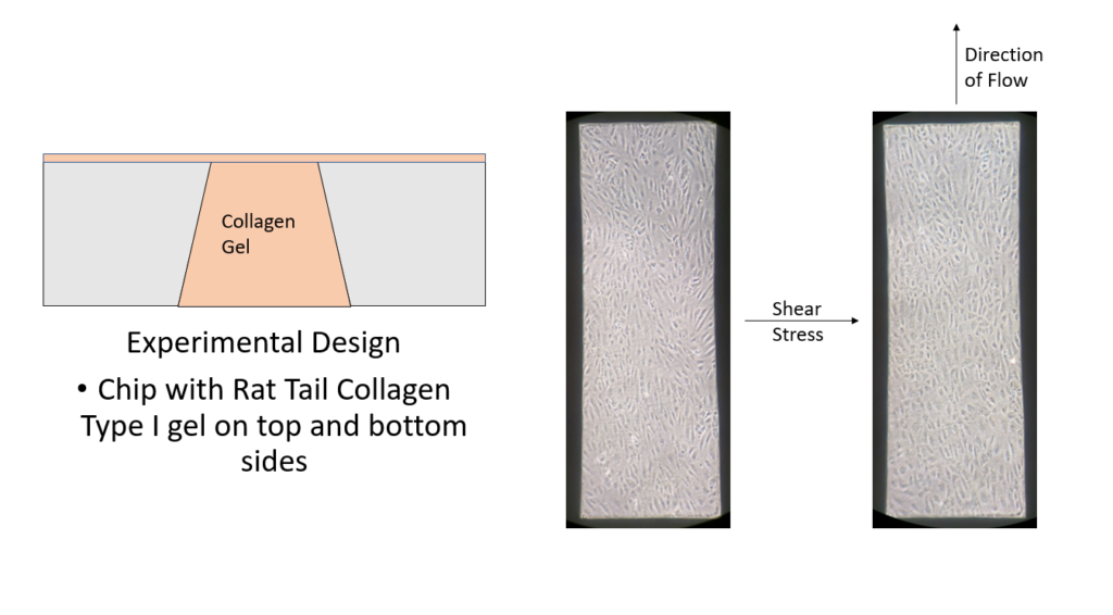
For the next experiment, rat tail collagen type 1 gel was added to the top and bottom sides of the nanoporous chip. HUVECs were than seeded on top of the collagen gel and subjects to 10 dyn/cm^2 flow for 24 hours. Unexpectedly, the HUVECs on the gel did not align like the cells on the nanoporous chip alone. The cells prior to flow were in a semi-aligned configuration, and the addition of flow did not appear to further align these cells (Figure 3).
Rotation Experiment
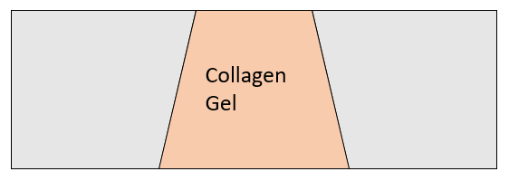
Following any experiment that posts interesting or contradictory results, the next logical step is to run experiments that eliminate any possible confounding variables in the experimental design. For this study, that would entail seeding HUVECs on the top side of a nanoporous chip with collagen gel only added to the trench (bottom) portion of the chip (Figure 4). The future direction of this study will be heavily influenced by the outcome of this experiment, so it is hard to comment on what a positive result would be at this time. However, expect an update with results and future directions in the near future.