Making Slot Devices in URNano facility
The schematic of the slot device is shown below. The main support structure is the pnc-Si membrane with Au or Ag metal on both sides.
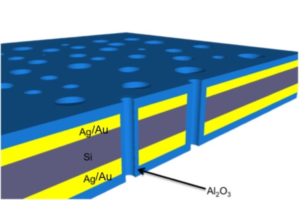
There is a conformal covering of Alumina shown in blue in the figure which actually makes the slot. This type of structure helps in squeezing the light in the nanoholes.
The first step to make this device is to deposit a 3 nm layer of Ti which acts as an adhesion layer and then deposit 13 nm of Au on top of it. The deposition needs to be such that the holes are not blocked and the metal layer is continuous. As seen in my previous post the PVD-Lesker tool in URNano facility gives a stark contrast between the freestanding membrane and the substrate. This can be seen in the SEM image of the metallized membrane shown below.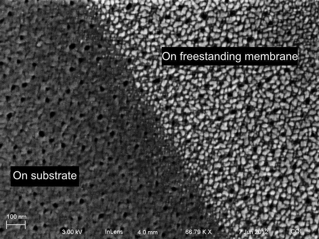
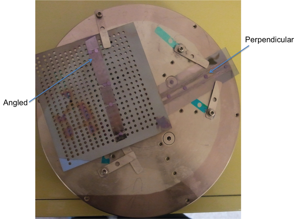
SEMs were taken of the angled samples and the perpendicular samples as shown below. The angled sample is the one nearer the middle of the platen. The perpendicular sample membrane is the one at the edge of the platen.
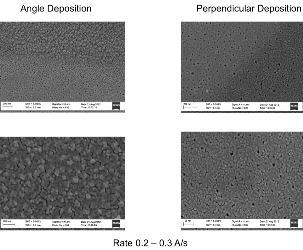
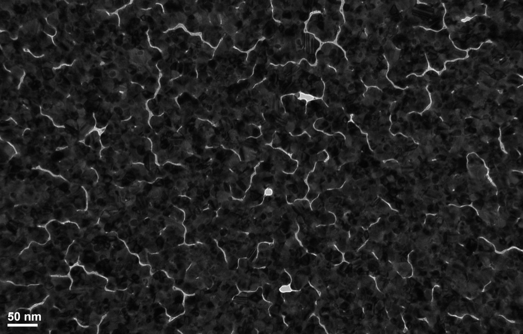
The SEM’s clearly show that the keeping the membranes at an angle does not help in depositing a continuous film over the membrane. Increasing the distance between the membrane and the source does help in making the film smoother but the metal is still not as continuous as it was using the RIT CHA ebeam evaporator. This is more evident in the TEM image of the metallized membrane shown in the image below.
ALD deposition of 10 nm Alumina was then performed on these metallized membrane. Higher temperature deposition gives better quality and integrity of the films. 250˚C was used in deposition. The SEM and TEM were taken of the ALD deposited film. The images are shown below.
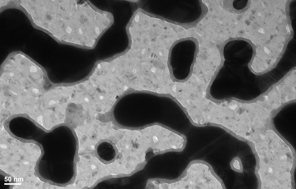
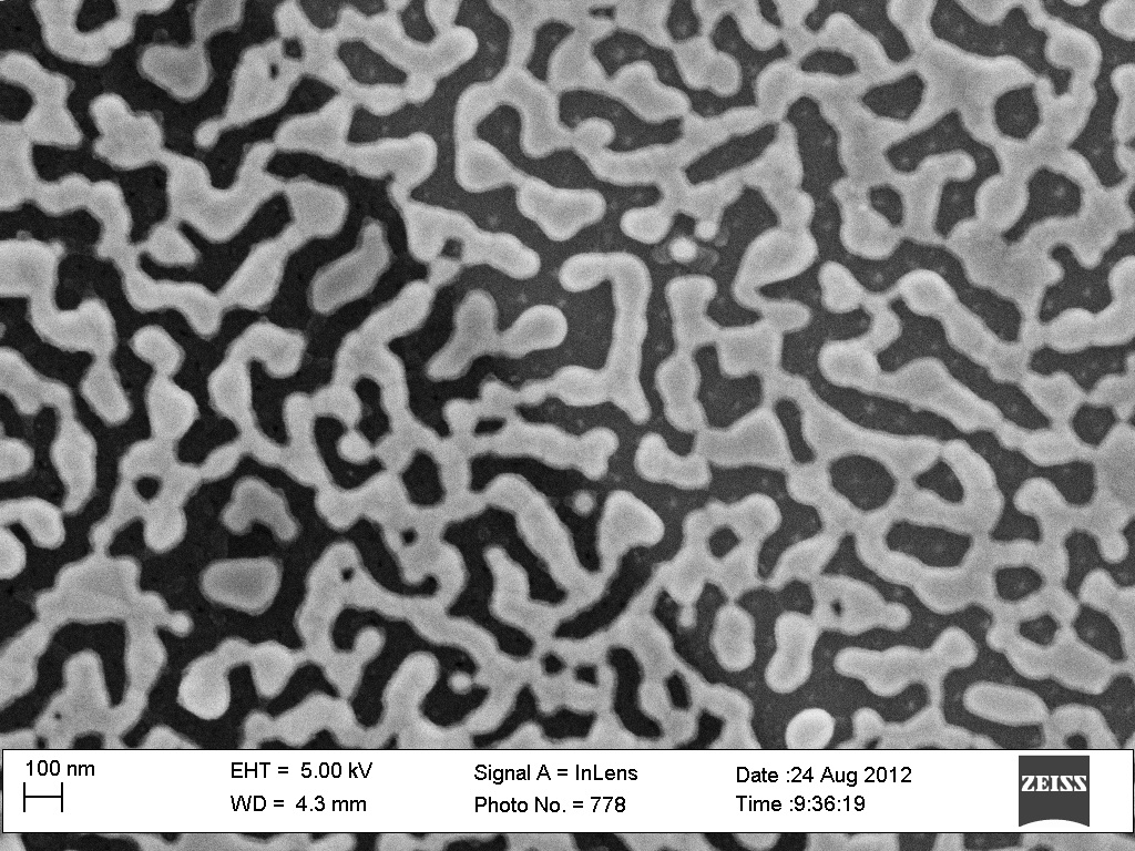
The TEM shows that the metal has coalesced and formed islands, and the Alumina has been deposited over the metal and around the holes conformally. The metal deposition over the pnc-Si not being as good, 250 ˚C is sufficient for island formation over the freestanding membrane. The SEM of this membrane, shown in the image below, shows the formation of metal islands over the interface. The metal island formation extends over the substrate part of the membrane.
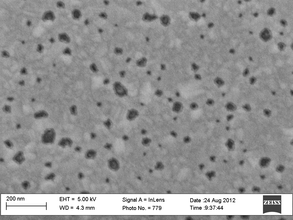
Much further away from the freestanding part of the membrane, over the substrate, the metal film does not form islands after the ALD process. It remains as a continuous metal film. The Alumina is deposited conformally around the hole. This can be seen in the SEM image of the ALD deposited metallized membrane shown in the figure. The image is taken over the substrate part of the membrane much further away from the freestanding part.
In conclusion, continuous metallized films can be deposited using the URNano facility, by increasing the distance between the membranes and the source, though the film quality is not as good as that got in RIT. ALD deposition at 250˚C leads to island formation of the metal film over and near the freestanding part of the membrane. Further away from the freestanding membrane over the substrate part of the membrane, there is evidence of the slot structure. So the next step would be to use a lower (100˚C) ALD deposition on the metallized membranes.
Low temperature (100˚C) ALD deposition process was performed on a metallized membrane.TEM image shows the formation of the slot structure.10 nm of Alumina was deposited. Shown in the figure below.
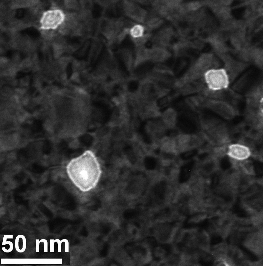
The largest of the pores shows a slot in the middle, with the alumina deposited around the hole conformally. The smaller holes are covered totally with Alumina.
This image shows that the even the low temperature works in creating a conformal layer along the nanopores of the metallized membrane. The structure is limited by the metallization process.