3D Printing for Milli/Microfluidics
I’ve been using a Makerbot 2 for the last week or so, trying to see if we can use the same PDMS contact lithography techniques that we are all familiar with. In short, yes, but there is plenty of work to be done to make it a robust process for microfluidics.
Makerbot Printer
The makerbot extrudes a thermoplastic from a very finely drilled, heated nozzle. This liquifies PLA plastic, which then flows out and cools on a surface, hardening. The nozzle can write in X, Y and the build plate steps in Z, making a 3d image. It doesn’t necessarily make a totally solid volume; infills of 10% are generally acceptable for non mechanical models. The solid is made up as a number of shells, where more shells add toughness through more material. For imprint purposes, we really want to have a smooth outer shell. Makerbot 2 is spec’d at 100 micron layer thickness. The diameter of the extruded filament forms the thickness of each layer.
Print settings
The macroscopic print: 230C, 40 mm/s, 300 micron resolution , 1 shell sliced using Makerware
The microscopic print: 230C, 40 mm/s, 100 micron resolution, 1 shell sliced using Makerware
Macroscopic designs
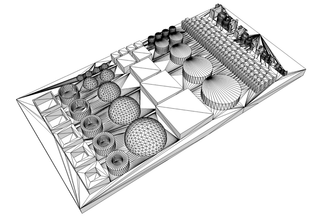


Here the designed thickness was 0.5 microns. There are 2 shells, inner and outer. The top face does not have a shell!

In this picture, you can see the edges of the filament, at 300 micron resolution. Rough to the touch, though the bulk conformance to the designed sphere is correct.


The lack of a top shell seems to impact a lot of the roughness on the surface. Walls look like spool of thread, with circular elements very apparent. You can see all sorts of vacancies and voids in these structures, though the vertical alignment is very accurate on all of these structures. Little bits of filament extend from structure to structure, though these can be severed with a blade reasonably.
Resolution Test

You’ll notice the irregularity in thickness, as well as extrusions that happen while the tip is traveling, unintentionally. Too much filament is being heated for what is being extruded, so going faster may help this problem.
Soft Lithography
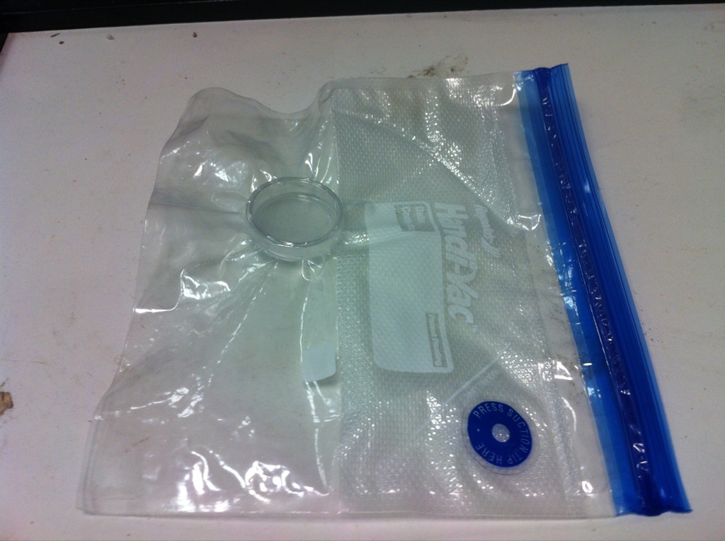
I used some premixed PDMS to flow over a printed mold. Agitating the PDMS produced bubbles, so I outgassed it with my Vacuum Bag . Works pretty well; you can see the bubbles rise and pop and you’ll need to evacuate the bag every 10 minutes to compensate for the extra gas. I let the mold cure overnight at room temperature. Hotplate/oven cures are probably possible at 70C, if the melting point is ~230C.
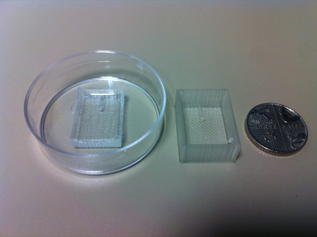
The structure is a 1 mm cylinder, embedded in the wall. I chose this geometry because I thought we could do horizontal insertion of tubing this way (which it did fit). Notice the thatched pattern on the mold, which successfully transferred over to the PDMS imprint. This means that it formed many microchannels at a potential bonding surface, which could be a source of leaks later on. Also, the top surface is not planar, having wicked up the walls of the mold. The PDMS is noticeably more pliable and stretchy than I’m used to; I’m pretty sure it’s 20:1 PDMS to cross linker.
In short, it works. We can probably plan on ~1 mm size features coming out roughly, and 0.5 mm features on a very good day. I will be aiming for 300 micron geometries while I’m here. The actual device was very compliant and stretchy, which I think helped it stick to the surface. Lots of things can be done to make it better.
Work to be done
- Design of experiments on extruder speed, temperature, number of shells to achieve best resolution and repeatability. Low volumes probably require higher speeds or cooler temperatures.
- Solution for smoothing PLA? It undergoes a phase change very quickly, so it might be difficult to get any repeatable process. Maybe a hair dryer…
- Multi-height PDMS mold
Future
- Dual extrusion with PolyVinyl Alcohol (PVA) would provide a water soluble scaffold to support more complicated structures made in PLA. Could we use PVA to do PDMS contact lithography, and then dissolve it away? This setup would require the Makerbot 2x (~$3k)

And now for something completely different:


Great Job!! it ill be really awesome if we can make the whole microfluidic device using 3d printing. I believe, the main challenge is in making smaller channels (100 ish microns). Round and non-rectangular geometries can be pushed to later. Are you aware if this is THE 3d printer out in the market, or if they also have higher versions that can make smaller resolution dimensions?
I’ve been really interested in this model particularly because of 1) low cost (3000 for printer vs 10-20000 for some other printers with much higher resolution), 2) use of PLA plastic which is directly biocompatible if we wanted to write structures and grow cells on them, 3) It’s spec’d for 100 micron layer thickness, which is what we do now. In an ideal world, I would want a 10 micron layer thickness, giving us a chance to resolve very fine features at the 100 micron level. Here, its’s more like mm size, which I believe we can use effectively for a number of different things not pertinent to fluidics. I can vouch for the material’s strength; repeatable printing seems to be the main difficulty. There are many different types of printer out there, including at U of R, but they use different technologies (laser-resin polymerization, binder-dust fusing), and are more expensive machines generally not giving this resolution commercially.