Tomograms of 1148 NPN
Wafer 1148 was produced roughly around the same time that the wafer I used to make my oldest MgF2 material (wafer 1085) was produced. We know that some of the NPN material from that time was not etched all the way through, creating pores that look like a ‘bowl-with-hole’. I believe the shape of the NPN substrate pores influence my SERS structures directly through the MgF2 templating process I have developed. By making MgF2 structures out of the ‘bowl-with-hole’ NPN structures, I hope to recapture the optimal SERS properties that we have seen before.
We have already seen the effects of partially etching the substrates before coating the chip with npMgF2/npAu, so we know there are at least pore-size differences (2D) on the overall SERS behavior. My tomogram work (3D) should help capture the differences resulting from the nanotopography of the NPN/MgF2/Au coated pores.
TEM tilt stack formation
Our eventual goal is to gather data from a number of pores to accurately represent the variety of nanostructures that are generated in our material. We need a decent resolution (~60 KX) to capture the internal surfaces of the pores, so it would be beneficial to get many fields of view to capture many pores (there should be about 200-300 structures in a single 1um focus spot). It’s not strictly necessary, but you can stitch together adjacent fields to gather a continuous surface.
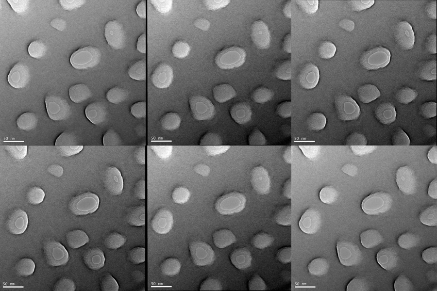
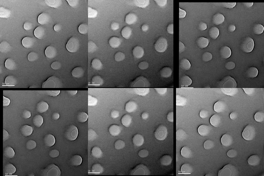
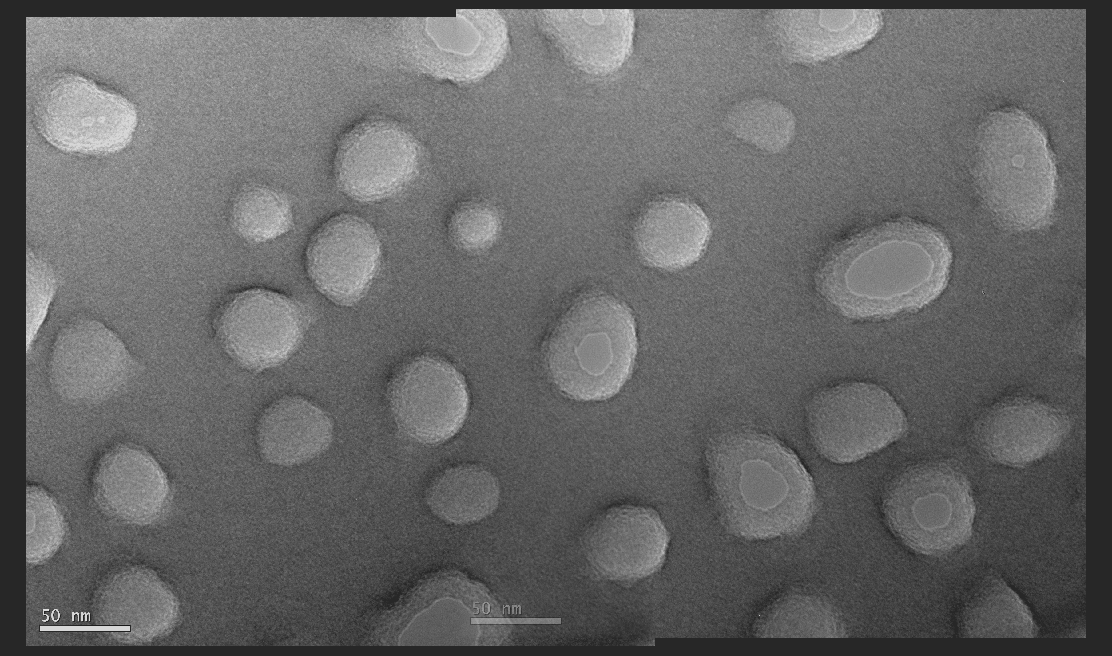
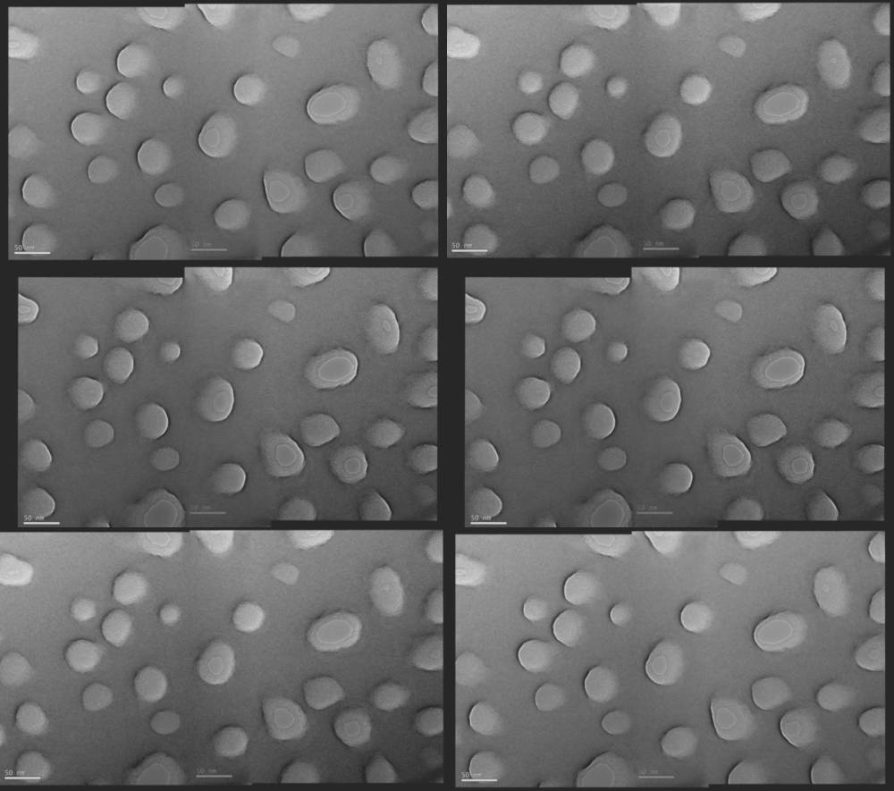
As the merged fields are currently aligned by my hand, there may be be a better way by using photoshop (photomerge) to automatically align these fields of view.
Tomogram Generation
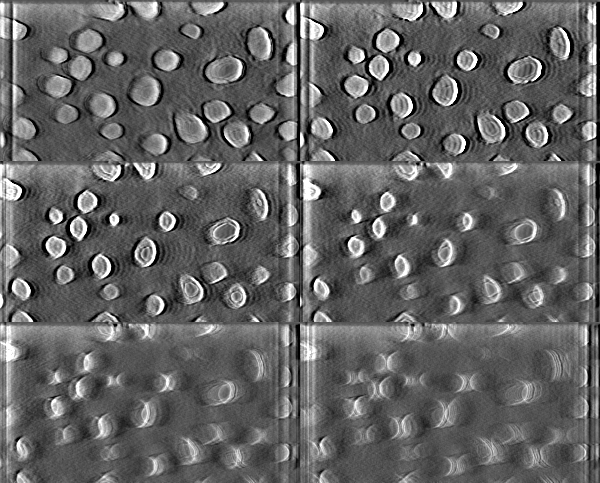
I used a simple weighted back projection for this tomogram. It’s not bad, though there are some echoing curves. It’s easier to segment them out separately.
Segmentation
The video above shows my layer process for generating the STL from the tomogram slices (Here I only used 1 single field of view, not the merged frames from before).
- Gaussian blur (6 pixel radius) on the tomogram data
- Create a seed layer (hole mask, orange), by painting in the hole volume through the slices (1 every 10 slices or so)
- Run Segmentation level set (green, this probabilistically fills in the differences between my seed layer
- 300 iterations
- 5 -threshold range
- 0.3 curvature weight
- 0.3 propagation weight
- 10 Edge weight
- Fast Dilate/Erode (2d, 3/3, red, to clean up the noise)
- Fill (blue, creates a solid volume to subtract from)
- NPN volume (duplicated fill, then used Remove tool, yellow)
The volume rendering is really illuminating, as the sidewalls are fairly anisotropic, reaching down to the floor of the bowl. The floors are very thin, only a few nm thick.