PEGDA Microarray and PEGDA reactivity issue
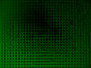
My goal and focus of the last post is to to use the existing SU-8 grid structure used on the ultrathin silicon oxide lift off membranes to create . To accomplish the goal the SU-8 surface needs to be modied to decrease cell adhesion so that the cells are trapped in the wells. Please see the images below that Brad Kwarta created showing the membrane and SU-8 grid before and after surface modification with a polyethylene glycol derivative.
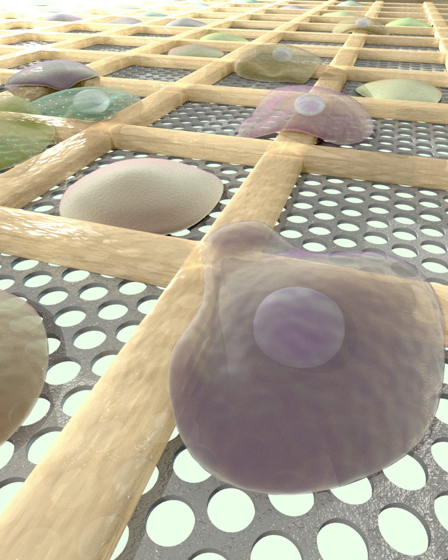

Before After
Due to events discussed below this post will focus on recreating and improving the polyethylene glycol diacrylate microarrays the lab has made in the past along with the discovery that the PEGDA being more reactive then it should be. Most of the work on the PEGDA membranes is work that would have been done at some point down the line as part of a paper.
Due to membranes suspected of having surface contamination affecting Stephanie and Nikki’s planned summer experiments this became the focus so that they have something to perform cell experiments on for their end of summer undergraduate research presentations .
For their poster two standard methods were to be compared. PEGDA arrays formed with a photomask and arrays formed a PDMS mold. A 3-(trichlorosilyl) propyl methacrylate (TPM) coating is used to increase adhesion to the piranha cleaned glass substrate and Trichloro(1H,1H,2H,2H-perfluorooctyl)silane ,a fluorosilane, is used on a second slide to decrease adhesion to glass and provide a barrier between PEGDA and the mask. Successful coating of the fluorsilane on glass can be checked by attempting to mark the glass with a sharpy. The fluorsilane prevents the mark from being clear.
Analyst, 2014,139, 1303-1326
Schematic of the mold fabrication.
I focused mainly on the photomask method while Mert Corbaci, a 5th Phd our lab temporarily “borrowed” focused on the PDMS mold method. Originally this should’ve taken a week at most of Mert and I’s time, including optimizing the designs. Confidence was high enough that instead of adding steps to check for errors we skipped straight to combing it all running and running most of the symposium experiments at once. The cell experiments quickly showed major issues and a general failure.
Link to representative of the issues seen.
https://drive.google.com/open?id=0By6d8BVq8ssGeHg2WW9rSjRva0k
edit-replace this image
Most of July was spent trying to fix the problems including a persistent layer of solidified PEGDA at the bottom of the wells.
A short list of things of some things tried/hypotheses tested;
a large number of setup redesigns, chemical combinations, collimated vs uncollimated light, intensity,energy dose, light source distance, different mask, drying/washing times even sticking them in the oven, trying to make it work on the microscope.
The undergraduates eventually had their research presentations on August 4th and data was presented though neither array design actually worked correctly. It wasn’t until I went back to SU8-PEG bonding that series of events and experiments led to the conclusion that the PEGDA was more reactive then it had been even a month prior. The details will be left out beyond that the issue was likely due to either years of improper storage or contamination at some point. The chemical was replaced and a simple test proved that it solidified easier then the new PEGDA. This combined with the arras forming correctly with the first sample lead to a probable conclusion that stray UV beams were enough to form the layer of PEGDA seen at the bottom of the wells
The month of old data still provided useful clues as to how best optimize the arrays. The photomask should be optimized within 18-30 samples using a hierarchy of conditions likely to affect the array. At each step the optimum value is kept and used as the standard for future steps.
Total UV (5 vaules) and stack order (TPM or fluorsilane closer to mask)
initiator concentration (3 values)
UV intensity (3 values)
% PEGDA, (PEGDA % loss is replaced with PBS)
reevaluate total uv again and test a narrower range of values
Sample 2,25um walls and 50 or 100 um wells, at 4x obnjecive using the PEGDA. The wells are not filled with a PEGDA bottom
In conclusion PEGDA arrays were created using two different method after correcting a problem resulting from a faulty chemical. Next Steps to wrap it will be some minor optimization working and testing with cells. The next post and future work will focus on the work done and being done on modifying SU-8.