Glial cells can grow as multilayers upside-down
In my 1st post detailing glial cells on pnc-Si transwells, I saw lots of cell clumps above the membrane window (see here). Since these cells were grown in the wells, I thought they could be piling on top of each other in the wells and getting trapped. Here, I decided to flip the sample so that the glial cells grew in the wells, but upside down to see if this cell clumping still occurred. I suspected that cells would fall to the bottom of the 24-well plate instead of forming monolayers.
Here, NG108 cells (P13) were seeded at 50,000 cells/cm2 on the well-side of pnc-Si and then inverted so that they were upside-down in the 24-well plate for growth. TEER was measured and then the cells were stained with Live/Dead on day 7.
PET transwells showed a largely viable, nearly confluent cell layer with some multi-layer clumps. Even though these cells are hanging upside-down, their intercellular adhesion is strong enough to maintain multiple layers away from the membrane surface.
TEER:

TEER of control samples (PET) didn’t change. The pnc-Si results were confusing. Most of the samples stayed right around their day 0 values (that is, there was no increase in barrier function). However, a couple of samples showed ~50% increase in TEER over 1 week. Since there was a fairly confluent monolayer of cells on PET (see above) that didn’t cause an increase in TEER, I didn’t know what to make of this. So I looked at the images:
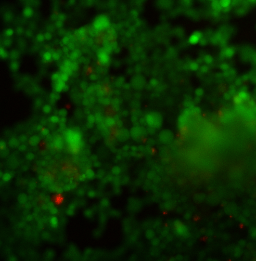
Sample 1 (same sample as in the graph) with the phase contrast channel shown in blue. There is clearly a huge clump of cells away from the membrane, but the cells don’t cover the entire free-standing membrane area.
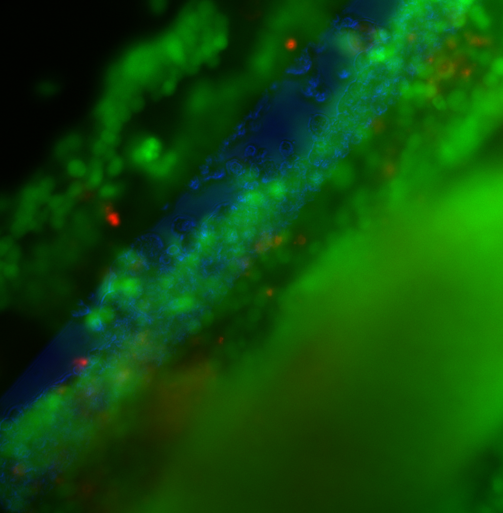
Sample 2 (same as in graph) is below. There are so many cells that the entire image is blurry. It appears that there is a layer several cells deep that covers the free-standing pnc-Si area.
 These drastically different morphologies likely explain the difference in TEER values for these 2 samples. The other samples (4, 5 and 7) exhibited similar coverage differences.
How are these cells clumping together when they are growing upside down? Here’s an image to show my working model:
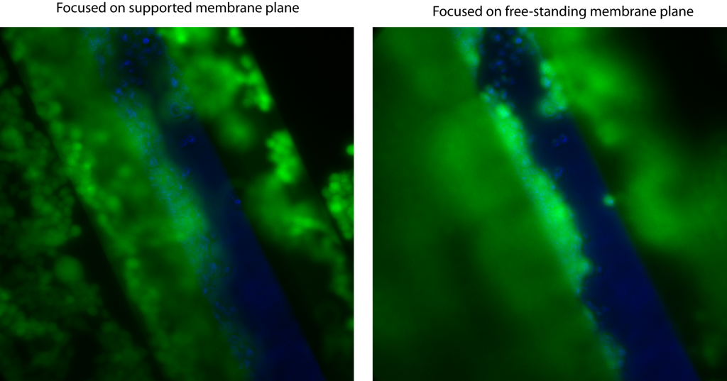 On the left is an image with the focal plane at the supported membrane and on the left is an image with the focal plane at the free-standing membrane. On the left image, cells on the supported membrane and the interface between the well walls and the supported pnc-Si area are both in focus. Clearly, there are cells growing on the sloped well walls. It looks like cells growing on supported pnc-Si form an almost continuous layer with cells growing on the well walls and then down onto the free-standing membrane. Now, this image isn’t perfect since there are very few cells on the upper-right area of supported pnc-Si. BUT, if the cells on either side of the wells (on the supported pnc-Si) form a somewhat continuous layer with cells on the well walls and the free-standing membrane, then dividing cells can stay attached to this cell layer within the wells – thus forming clumps.
This phenomenon would certainly be time- and ‘initial cell seeding density’ – dependent. I’m not sure why there are differences in clumping in this experiment. It could be differences in handling since these cells are not very adherent. I need to minimize this clustering in order to minimize the TEER of the glial cells.