Consistency with Effective Field
In prep for manuscript writing I came across a paper that says they’ve created a super efficient EO pump that uses extremely low voltages. Their top flow rate (.125 mL/(min V cm2) ) is comparable to the flow rates I see with our materials (144 mL/(min V cm2)). They run their experiments at 3 V and their membrane is many microns thick. So what gives?
On further investigation, I realized that they aren’t using the applied voltage for their normalization but the effective voltage across the membrane. They use the following equation to calculate effective voltage:
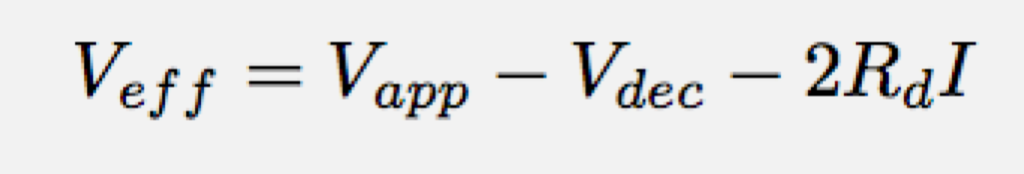
where Vapp is the applied voltage (which our power supply tells us), Vdec is the decomposition potential of the wires (or the minimum voltage needed to start electrolysis), Rd is the resistance in the fluid wells, and I the current of the experiment. This means that Veff also equals the membrane resistance times the current (Veff = RmI).
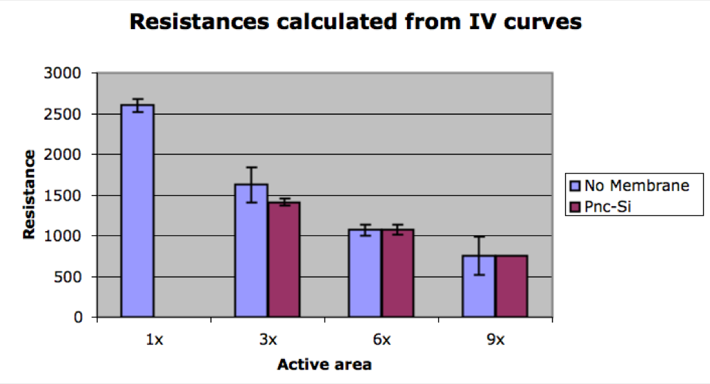
I tried to go about finding Veff in the following manner. First I used the IV curves to determine the combined resistances in the system: 2Rd+Rm.
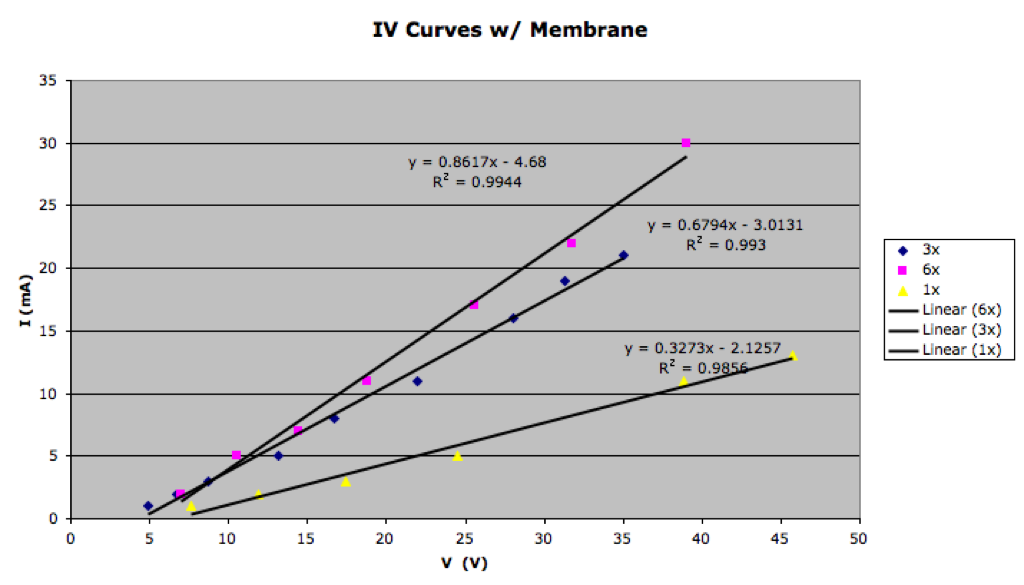
From this chart the resistance for the 3x membrane is 1471 Ω (1/slope). Next I found the resistance without a membrane: 2Rd.
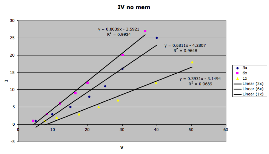
The resistance in this case for the 3x open windows was 1468 Ω (1/slope). In all cases, the resistances are very close, meaning that the membrane has almost no resistance at all. If we subtract 2Rd+Rm – 2Rd we get a resistance of 3 Ω for our membrane for the 3x case. To find the effective voltage we multiply by the current, and in the case of the usual 10 mA current we get a voltage of 30 mV.
Right off the bat, we have a lower effective voltage than the other membrane, but is this consistent with our other measurements? Let’s redo the original field calculation one more time:
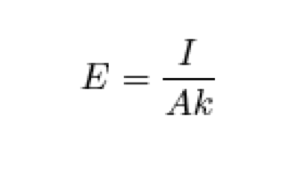
So field = the current over the active area and conductivity. Given a current of 10mA, an active area of 4.8e-9 m2 (200×200 um * 3 * 4% porosity), and a conductivity of 1.367 S/m, we get a field of 1.5e6 V/m. Taking that field over a 15nm distance, you get a voltage drop of 23 mV. So we’re really close here (23 mV compared to 30 mV). This seems to be pretty good agreement between the two methods.
Conclusions:
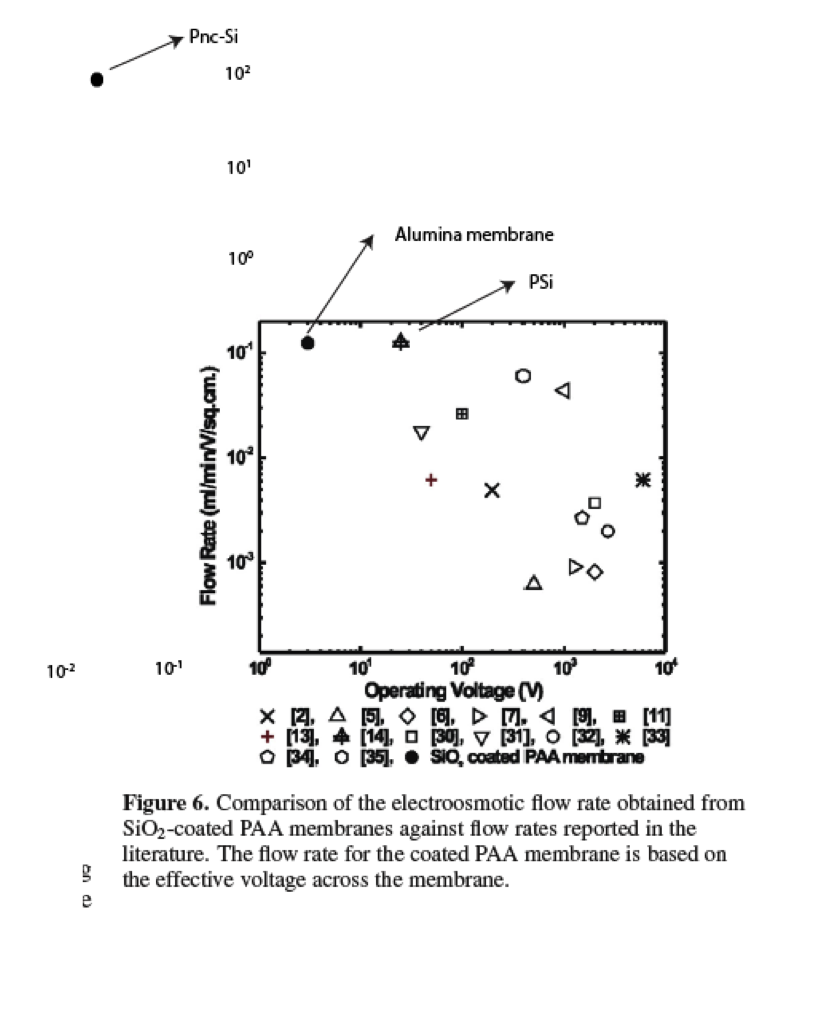
1. Our membrane has a very low effective voltage and high flow rate. If we use effective voltage for our normalization our flow rate becomes: 96mL/(min V cm2) which is off the charts compared to anything else. Let me just steal their chart to show you:
2. It seems that our methods of field/voltage determination are pretty close. Granted there’s a bunch of error in the resistance fitting method I’ve shown here, but that’s mainly due to the fact that our membrane resistance is super low and hard to quantify. I’m pretty happy overall with this.
3. We really are a low voltage/high rate pump, and maybe the only one at that. And if you read through this paper, they keep saying thinner is the way to go for lower voltages and higher flow rates.
Here’s the paper if you’d like to read: sio2_alumina_eo_pumps
UPDATE:
Here are the resistances from the IV curves with a bit of statistics too. It looks like membranes have little to no resistance, or it’s within the measurement error. This makes the above calculation for voltage drop based resistance differences a bit moot, but the take home is that the voltage drop is very small (millivolts or lower) since the resistance is small.
very nice, the one little request I would have is can you do an experiment (or have you already done an experiment) in which the distance between the electrodes is decreased so that you can check the value of Rd and put the final nail in this coffin?
Jess
I measure membrane resistances all the time as Day0 values for my cell culture experiments. If you look back at some of those posts, I concluded that the membrane resistance was essentially 0 – all of it came from supported Si. However, the numbers you reported above are about 2X what I typically see. Whats the active membrane area of those chips?
The active area of the sample measured here is ~3.3 times lower than the standard 2 slit membrane. It doesn’t look like resistance scales linearly with active area in the rest of my experiments, but this means that our tests are in the same range.
I thought we’ve discussed the membrane resistance at the NRG meetings before, but I guess I mis-understood. So the resistance with or without the membrane there is essentially unchanged, i.e. the resistance is near zero? Does this make any physical sense? We know that the membrane provides little resistance to diffusion, but substantial resistance in forced flow (at least relative to having no membrane there). I would have guessed that the flow of current would follow a similar relationship to the forced flow of fluid, with the membrane creating substantial resistance relative to an open window, as it should be governed by the porosity.
The only way to explain this is if the fluid in the pores is substantially more conductive than the bulk fluid. I suppose this could be true, given the debye layer. But then it seems like other membranes with similar pore size would have similar low resistances.
This is quite interesting, I have to think about it some more…
I think that the electrical resistance is more similar to the diffusive resistance than pressure resistance. In the pressure case all of your resistance is fluid resistance. When we put an electric field across the membrane, yes you’re giving the ions directed movement, but these same ions have little to no resistance when they’re simply diffusing.
Water movement is of no concern when looking at electrical resistance, so everything is just dependent on the migration of very small ions through the entire pore area. I personally wouldn’t consider the reason to be more conductive pores.
Keep in mind that the membrane is a huge constriction of charge flow when you have directionality, so it’s very different than diffusion. In a normal circuit, it would be the equivalent of going from a very large copper wire to a very fine wire, like a light bulb filament. For a 2% porosity membrane, the equivalent wire would be 1/50th of the cross-sectional area. Even if it is only over 15nm, all the current must still flow through a much smaller area (unless the membrane itself is conductive – have you measure current across a non-porous Si membrane?). Given the large external resistances, it may still be invisible in these experiments, however, all this data is of little value if we cannot measure the affect of the membrane…
I haven’t measured current through a non-porous membrane. There is no current through a silicon chip with no membrane though. To do this experiment you’d need a completely non-porous membrane – not one of the ones that we occasionally see diffusion of salts through.