Variation of TEER as a function of membrane area (COMSOL simulations)
Background: This is a follow up to the blog that Jim wrote on the basics of TEER measurement. This is the link to my old blog, which also describes the theory and some other preliminary data about TEER measurements.
The resistance (R) of a wire is the resistivity (ρ) times its length (L) divided the cross sectional area (A) of the conductor: 
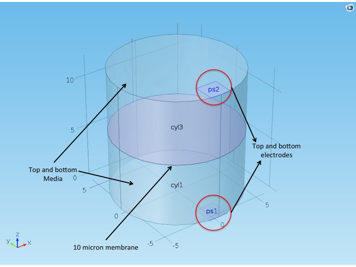
Model: The model geometry is shown below. Two big chambers, representing the media are separated by a 10 micron membrane. At the corners, there are two smaller square surfaces (ps1 and ps2) representing the chopstick electrodes. They occupy a significantly smaller surface than the total membrane area, and thus model the point-probe nature of the chopstick electrodes. The top electrode is assigned to be the current source (J = 1 A/m2), while the bottom electrode is grounded. The media is assigned the conductivity of 1.5 S/m (found some online sources using this value for their modeling purposes). Assuming the membrane is ~15% porous, I gave the membrane space a conductivity of 15% of the media conductivity. (A typical 3 micron pore polycarbonate transwell sold by Corning has about 14.2 % porosity, as calculated from their manual)
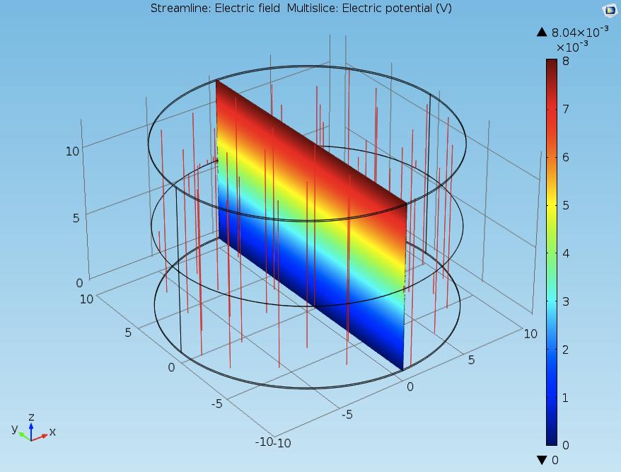
The simulation is ran for DC mode only. (I have yet to figure out how to implement AC in COMSOL). Free tetrahedral meshing is performed. The simulation displays the potential difference as one of it output parameter. We can plot electric field as well, and display the corresponding streamlines. A typical result looks like this
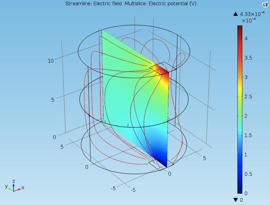
I couldn’t find any display option that shows the net impedance of the system. Henry suggested that I back-calculate the resistance from the potential drop since we know the input current. Thus, by measuring the potential drop across the electrodes, I used to estimate the resistance values for the model.
Results: People use transwells of different areas. Standard ones are 6.5 mm dia (24 well plate), 12 mm dia (12 well plate) and 24 mm dia (6 well plate). I tried to model these geometries, and some diameters in between. Also I ran this entire process for a bigger electrode, to understand the effects of the size of the electrode. The results are as follows.
Effect of varying membrane size on the net resistance of the system.
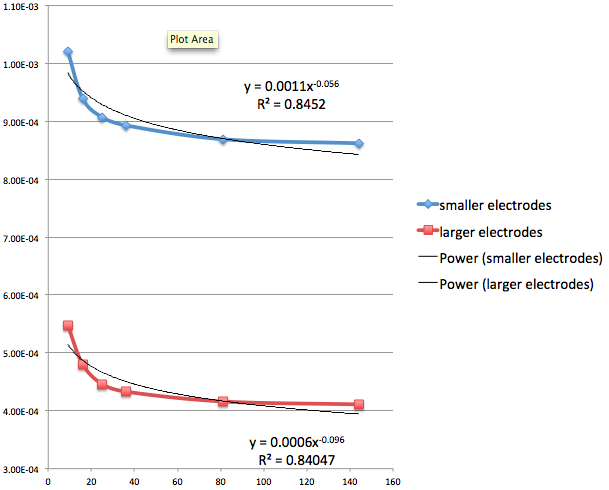
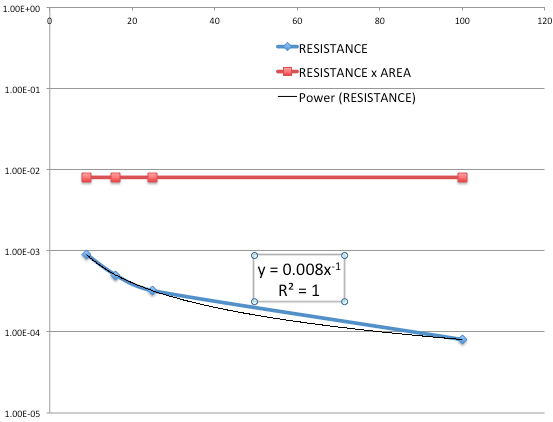
The behavior of resistance vs area looks hyperbolic. However if we plot the product of R and A against A, we do not get a constant as expected from the simple formula for resistivity.
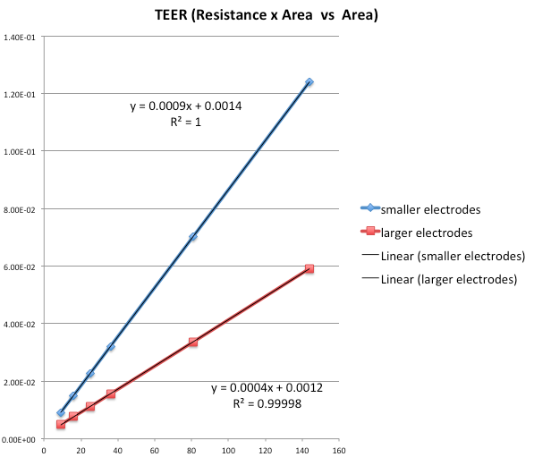
RA is actually linearly increasing with A and the slope changes for the two electrodes. This clearly means that simply multiplying by the resistance will not ‘normalize’ TEER measurements made with different membrane or electrode sizes.
Now let’s try to understand this result to gain some insight. Note that both electrodes give a line with a nonzero intercept. So ..


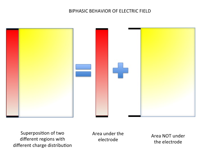
So the results imply that there is one part of the resistance that is area independent (as predicted by the simple formula for the resistance) and a second part that is increasing with area.
One way of rationalizing this behavior is to imagine that the region directly between the electrodes is wire-like since the field lines (and current density) will be more uniform there. So in this area the simple RA = constant formula does hold. This explains why the constant value is larger for the larger electrode compared to the smaller one. The region outside of the electrodes is where the field lines bend and the current density gets less and less dense as we get further away from the electrodes. This is the area dependent component.
As a check on this logic I modeled a uniform electrode above and below the membrane instead of the chop stick configuration. All the field lines are now straight …
And the product RA is now constant.
Take home: The chop stick electrodes used conventionally for TEER measurements provide very crude estimate of the actual resistance measured. In order to get the correct values, we need to model the geometry of the system exactly and try to evaluate the empirical parameters governing the dependency of the resistance with the cross sectional area. Only then we can normalize the different TEER values from different systems. This result also makes the case for having systems with uniform field lines passing through the membrane.