Characterization of ITO electrodes using Impedance spectroscopy
I have been using ITO electrodes deposited on PTFE sheets for my TEER measurements. A 100 nm thin ITO is deposited on ~300 micron PTFE sheets, and have a sheet resistivity of 60 ohms/sq. This sheet is commercially available from Sigma; so the electrode properties are consistent within the experiments. Although ITO has a huge advantage in terms of optical transmittance and excellent cyto-compatibility, the electrical properties of the electrode in the presence of a conducting electrolyte were always a matter of debate. ITO is a polarizable electrode implying that there could be a charge built-up at the electrode-electrolyte interface, and may render an open circuit at that junction of the electrode. This problem can be tackled using suitable ranges of input current frequency by avoiding the capacitive effects. However, I had never characterized this behavior, and did not confirm the potential application of ITO for resistance measurements. In this study I have used the approach of Impedance spectroscopy to understand the frequency response of ITO, and how to avoid the potential artifacts arising out of electrode polarizability.

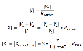
I assembled a simple microfluidic device with a 1 cm long single fluidic channel cut into a 1 mm thick silicone gasket. This gasket is then bonded between two ITO electrodes, each of 2×2 cm2 in dimension. I plan to fill this channel with PBS. This device basically represents a ‘PBS resistor’ of dimension 2 x 0.1 x 0.2 cm3. Both the top and bottom ITO electrodes have a silver wire attached at diagonally opposite vertices. This assembled device behaves as a RC circuit, as shown in the later part of this blog as well as in the schematic shown above. This device is further connected to a 1000 ohm resistor in series (R_series), and the circuit is completed by connecting a frequency generator, capable of delivering AC signals from 0.1 Hz to 2 MHz. I used a dual trace oscilloscope to probe the voltages at point 1 and 2, as shown in the schematic. My plan is to perform a frequency sweep and measure the impedance of my device. The impedance calculation is pretty straight forward, as shown below. Note that I am estimating only the magnitude of the load impedance, and not the phase data.
I repeated this experiment for 3 different concentrations of PBS: 10x, 1x, and 0.1x. The impedance data looks like this:
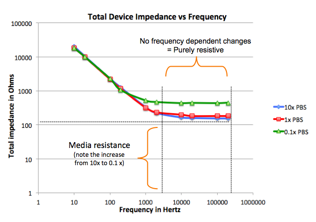 The electrode-electrolyte interface can be modeled as a RC circuit with a resistor and capacitor in parallel (and not in series!). At low frequency regimes, the capacitor behaves like a open circuit, so the net impedance is dominated by the junctional resistances and the media in between (red path in the inset circuit diagram). As we increase the frequency, the RC circuit gets more compliant, and the junction impedance drops down. Once we increase the frequency beyond a certain threshold value, the capacitor now acts like a short circuit, routing the whole current directly to the media in between the electrodes (green path in the inset circuit diagram). This effectively bypasses any junctional impedance, and we see pure resistive behavior once again. This time the estimated resistance is completely dominated by media, with negligible impedance from the junctions.(The horizontal dashed line represents the value that is devoid of any junction effects, i.e., resistance contributed by PBS alone. The two vertical lines represent the frequency region in which the impedance plateaus out.) Furthermore, we can see that this ‘leftover’ resistance increases as we decrease the conductivity of the PBS.
When we have cells on a membrane in between the two electrodes, the circuit will get altered slightly. Instead of having plain resistors representing the media, we will have another RC parallel circuit; ‘R’ representing the paracellular mode of transport a.k.a TEER, and ‘C’ standing for transcellular, or, transport through the lipid bilayers of the cell membrane. Again, from the above analysis, I expect that at lower frequencies, we can safely ignore the capacitive effects, and can assume the net impedance equal to the TEER contributed by the cells. Background subtraction will get rid of the electrode (ITO film) resistances, as well as the junctional and media resistances.
EDIT: I heard there was some confusion regarding some aspects I mentioned in the last part of my post. This is to clarify the finer details. There are two types of transport occurring through the cell layer. The transcellular transport occurs through the tight junctions and other intercellular junctions, and paracellular transport occurs through the lipid bilayer of the cell membrane. The transcellular transport depends on the gap between the cellular entities, and hence behaves resistive in nature. The paracellular transport depends on how good the charged species can accumulate in between the lipid bilayer before breakdown happens, and hence behaves capacitive in nature. In terms of electrical equivalence, there is a parallel RC circuit, since both modes of transport can occur simultaneously and not sequentially. The current can flow either through the resistor or through the capacitor or may be through both components depending on the load offered by either of the paths. We are interested in assessing the resistive nature of cellular monolayer, since the integrity of monolayer can only be understood by knowing the behavior of tight junctions. Hence we need to know the value of R in the RC circuit, which can be possible only the impedance is purely resistive in nature. Any fragment of current flowing through capacitor will distribute the load, and we wouldn’t be able to estimate R. Thus our ideal requirement is capacitor is “turned off” i.e. no capacitive impedances are present in the system.
Resistance is independent of frequency, whereas capacitance varies inversely with frequency. If we want to study resistance, we use low frequency, as the capacitance is zero there, and vice versa. Hence in my studies, at higher frequencies, the capacitors are completely conductive and shorted, and hence behave like a wire. Since the circuit is already shorted, the resistance in parallel cease to offer any impedance, and is masked off. Hence the TEER box use very low frequencies to measure resistances.
This is very exciting. We discussed at NRG in your absence.
One typo … “I expect that at lower frequencies” should be “I expect that at high frequencies”