SepCon Device Analysis
Device Breakdown
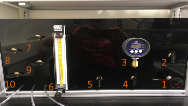
1 – Pressure Regulator
2 – System Isolation Valve
3 – Pressure Gauge
4 – 3 Way Valve – point left for only pressure gauge, point right to select a volumetric flow meter
5 – 3 Way Valve – point left for only digital volumetric flow meter, point right for digital and physical volumetric flow meter
6 – Physical volumetric flow meter
7-10 – Port isolation valves
There is a large empty area in the middle of the device, where a digital volumetric flow meter will go. It just hasn’t arrived yet.
Evaluation
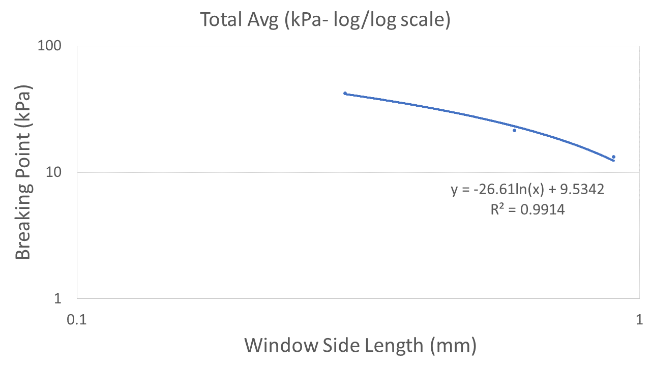
In order for this device to be effective, it needs to report accurate data. The SepCon device follows expectations set forth in the Steven Gillmer (2017) paper on our blog, which shows a logarithmic relationship between burst pressure and window size. After testing membranes from Lot 1258 that vary in window size (.3 mm, .6 mm, .9 mm), the logarithmic relationship holds very well.

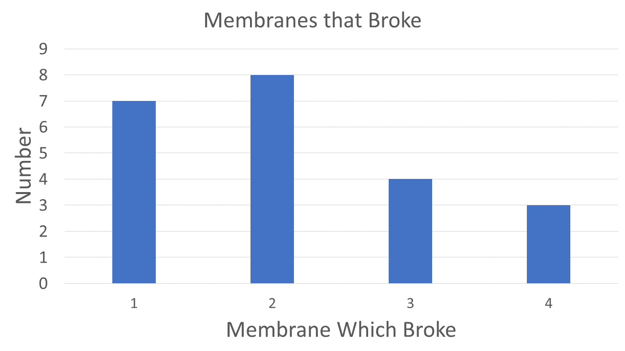
A possible error was found when testing 4-membrane chips from the bottom-right of Lot 1274. After multiple trials, it became clear that the first and second membrane from the top were far more likely to break initially than the third of fourth. The cause for this is uncertain, and requires more investigation whether there is a flaw in the making of chips or in the SepCon device itself.
Usage

Since this device has lots of valve, there will be a information sheet and markings to indicate where each valve should point for whatever process needs to be done, and a check-list when it is done being used.