Designing a two-channel 6-plex μSiM platform
Overview
The main aim of my rotation in the McGrath lab was to design a new 6-plex two-channel μSiM platform. Currently, individual two-channel μSiM platforms are used for tissue-on-a-chip experiments. Expanding the current two-channel single (1-plex) platform to a two-channel 6-plex setup will increase experiment throughput and efficiency, as well as provide a starting point for the lab’s manufacturing partners to produce these devices at a larger scale.
My rotation focused on prototyping this design, validating the sterile assembly, and performing preliminary cell culture experiments with HUVECs. Early prototyping of the device was performed on individual singlets (one channel at a time) rather than the full 6-plex device in order to save time and resources during the iteration process. The design process entailed 4 major versions before being tested in a cell culture experiment.
Design Process
Starting Point:
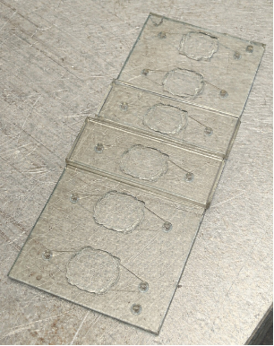
The project began with a 6-plex base plate manufactured by Aline, Inc (Figure 1). This base is constructed from acrylic, pressure sensitive adhesive (PSA), PET, and a cyclic olefin polymer (COP) bottom layer. The base provides 6 individual wells (singlets), each with an inlet and outlet port for what is to become the bottom channel. The challenge of designing from this was to add a top channel component that would create a sealed, two-channel system while maintaining the nanomembrane chip interface.
Spacer Component:
Because the 6-plex base was teller than the membrane chip itself, a spacer was needed to raise the chip to be level with the base top surface. The spacer (Figure 2) features a cauliflower-shaped geometry matching the wells of the 6-plex, with a 4 mm x 4 mm square cutout (that is smaller than the 5.4 mm x 5.4 mm chip) that allows the bottom and top channels to connect through the membrane.

The spacer is composed of a 0.5 mm thick PETG core with PSA (MP467) on both the top and the bottom (to allow for better adhesion to base plate and chip), giving a total thickness of ~0.8 mm. Combined with the 0.3 mm thickness of the membrane chip itself, this achieves the required height of ~1.1 mm to sit flush with the base surface. Autoclaving tests showed no apparent changes to the spacer, confirming it is sustainable to use for sterile cell culture experiments.
Version 1:
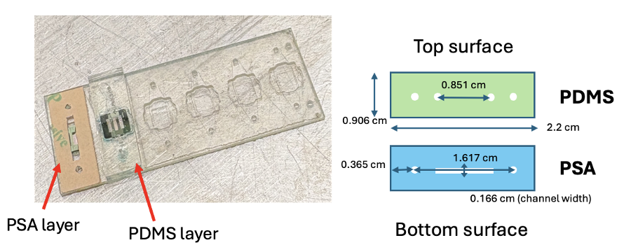
The first prototype (v1) introduced a polydimethylsiloxane (PDMS) top channel bonded to a PSA layer (Figure 3). PDMS is commonly used as it is easy to make, provides structural support for the channel, and is gas permeable, which is necessary when working with cells [1]. The PDMS was made by mixing 15 g of the base solution with 1.5 g of the curing agent (10:1 ratio), thoroughly mixing in a Petri dish, applying vacuum for 30 minutes at room temperature to remove air bubbles, and then baking at 70°C for at least 2 days before cutting to the correct shape using a template.
The PSA channel and PDMS surfaces were plasma-treated using a Corona Wand to increase material surface energy to create better bonding, then adhered together and aligned and bonded onto the base. Static leak testing was performed using blue dye (in the bottom channel, outer ports) and red dye (in the top channel, inner ports) (Figure 4).
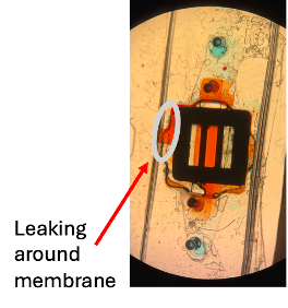
Initial static leak testing revealed some blockages due to misalignment of ports between components, but once handling was improved (without any design changes, just practice with aligning), blockages were eliminated. The only leaking observed was around the membrane/spacer area, indicating a potential need for a gasket.
Version 2:
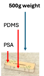
The next prototype (v2) was tested from my hypothesis that a better seal between the PDMS and PSA layers might prevent the observed leaking from v1. V2 applied additional pressure and heat: after adhering the PDMS and PSA layers, a 500 g weight was placed on top (Figure 5) and the assembly was placed in a 70°C oven for 24 hours. In this version, the width of the PSA was also adjusted to exactly match the PDMS width (in v1, the PSA component was slightly narrower).
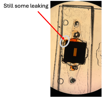
Despite the additional pressure and heat, static leak testing continued to show leaking around the membrane area (Figure 6), though decreased compared to v1. This indicated the seal issue was not between the PDMS and PSA layers, but between the base component and PSA around the membrane chip. This informed how our v3 design would look.
Version 3:
To address the leaking, v3 introduced a PSA + PET gasket layer to seal around the membrane chip and prevent the leaking observed in v1 and v2. The PET and PSA layers were laminated together before cutting, eliminating the need for a post-cut lamination, thus reducing potential for additional alignment issues with the ports. The gasket layer has a square cutout of 4.6 mm x 4.6 mm (smaller than the membrane chip dimension) to ensure the gasket overlaps the chip edges and prevents leaking around the membrane (Figure 7).
The gasket layers were laminated to the top channel layers by flipping the PSA top channel onto the PET layer of the gasket. Two alignment posts were used to ensure accurate alignment, as it got slightly harder to consistently align all ports with so many layers. Static leak testing showed no leaking between the channels or around the membrane (Figure 8), indicating the gasket layer performed well.
Flow Testing with v3:
Because static testing was successful, the next step was to check performance under flow conditions (a more physiological condition that will be used in most cell culture experiments). A 60 mL syringe was connected through 90° 20-gauge syringe connectors and fluid was injected at a rate of 200 μL/minute (see setup in Figure 9). Again, red dye was used in the top channel and blue dye was used in the bottom channel.
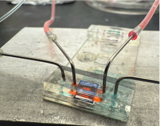
After ~1 hour of flow testing, some leakage was observed from the bottom of the 6-plex, coming from the COP layer due to a hole in the base (can be seen as blue dye spreading along the bottom of the base plate towards other channels). This hole was caused by tweezers that accidentally punctured the base while removing components from a previously assembly (since the same base plate was being reused for experiments across all designs), not from any assembly error or leaking between channels. Since future experiments using the device would be assembled on a new base plate each time, the minor leaking observed in this test was not of concern and did no reflect any shortcomings of the design. With adequate flow testing, prototyping transitioned to assembling the full 6-plex device.
Version 4:
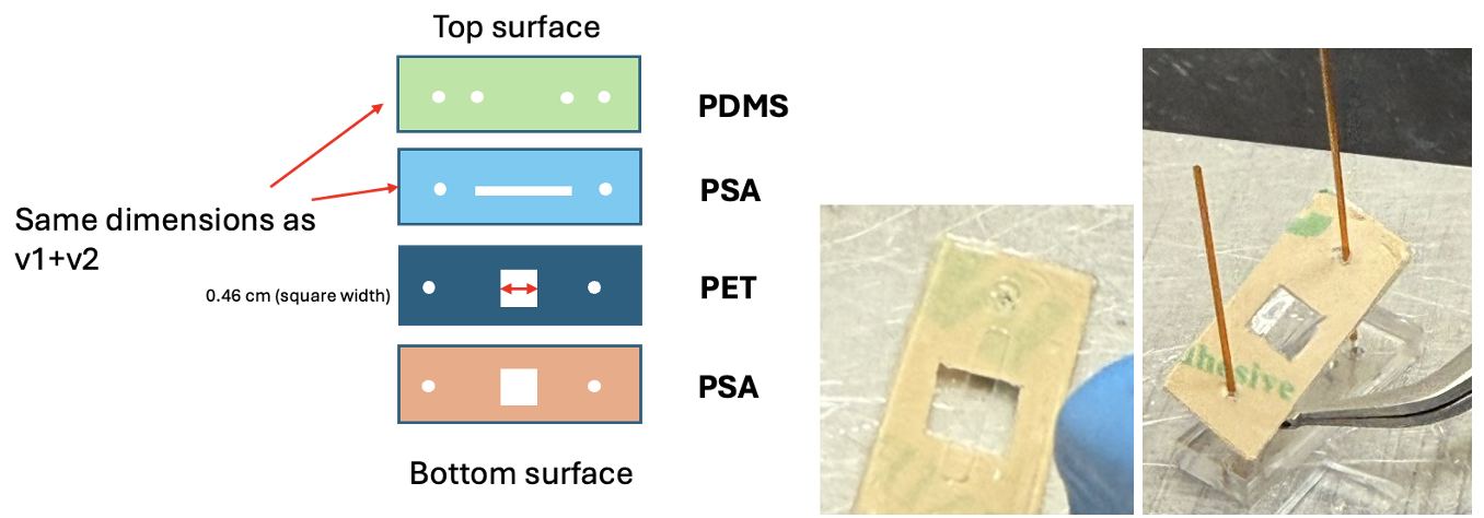
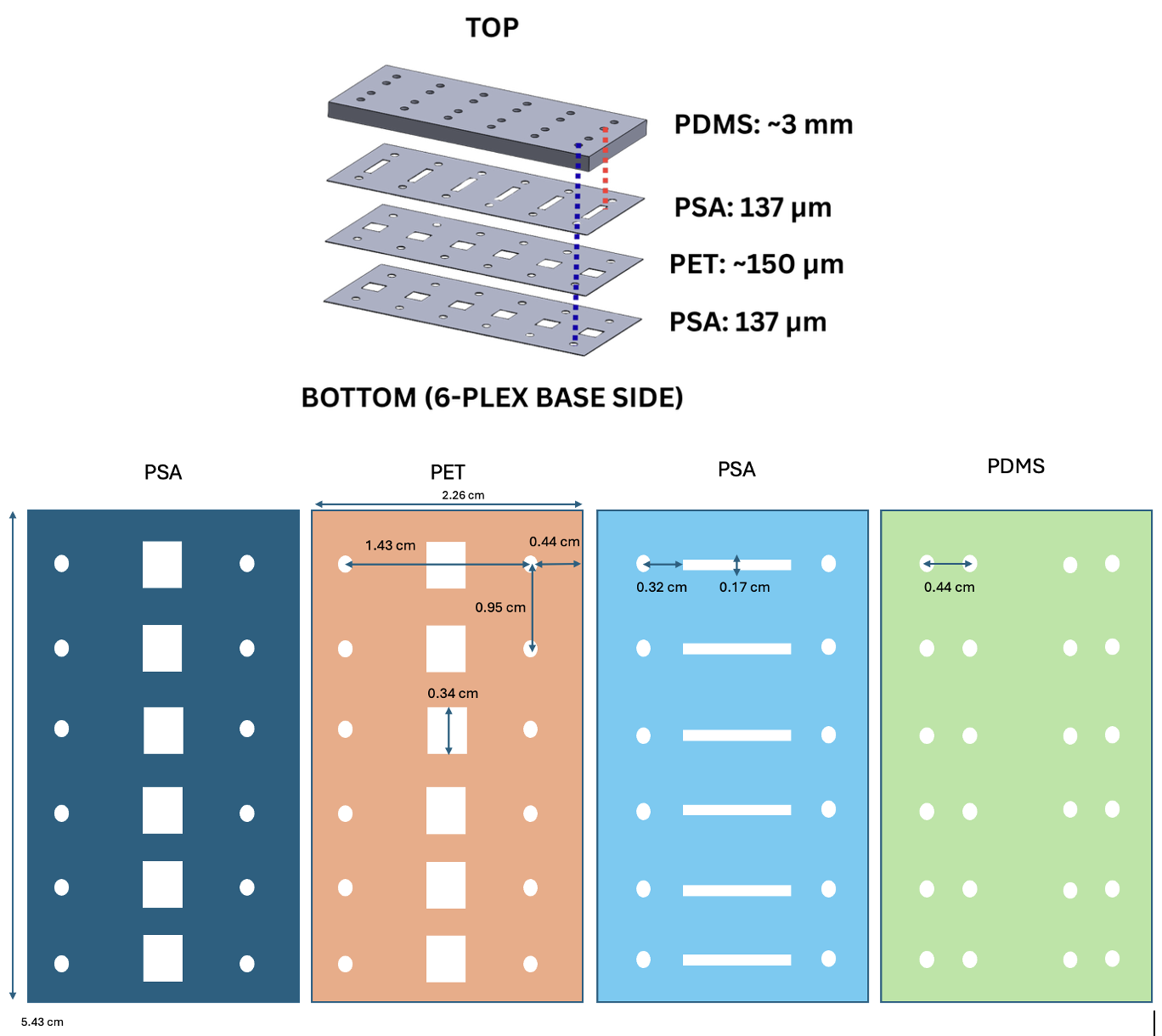
With the validated singlet prototype, the final iteration (v4) was assembled for the complete 6-plex device. This 6-plex device consists of 4 distinct layers, from top to bottom: PDMS (~3 mm), PSA (137 μm), PET (~150 μm), and PSA (137 μm), all mounted to the 6-plex base. The design and dimensions are shown below (Figure 10).
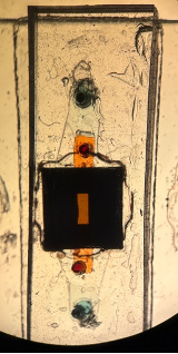
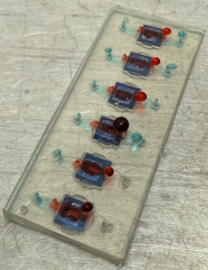
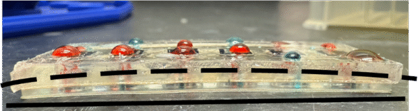
Static leak testing (Figure 11) revealed success in all top channels (red dye) and 4 of 6 bottom channels (blue dye). The remained 2 unsuccessful bottom channels exhibited flow blockages caused by poor alignment of the outer ports. This alignment issue was corrected by creating a new PDMS template with all ports accurately positioned to match the other layers. With this new template, all ports were aligned and functioned without blockages or leakage.
Sterile Assembly Validation
While leak testing with the full 6-plex device was successful, before proceeding with preliminary cell culture experiments, components needed to be tested in the autoclave to confirm compatibility and durability. Testing showed that PET alone warped significantly during autoclaving, and the PSA+PET layers combined also exhibited some warping (Figure 12), but when autoclaved with the rest of the assembled components (PET+PSA+PDMS layers laminated together), no warping was observed.

The fully assembled device (including the base plate) was also tested in the autoclave. Some warping of the base plate was observed (Figure 13), indicating the full device could not be autoclaved together, and would instead need to be assembled under a sterile hood.
Cell Culturing
With the 6-plex device validated through static and flow leak testing, and a protocol for sterile assembly established, the final step was to test cell seeding and viability. Devices were coated with fibronectin to help promote cell adhesion, then human umbilical vein endothelial cells (HUVECs) were seeded onto the device (in the top channel, above the membrane chip), and no leakages or blockages were observed from any ports before, during, or after seeding. The cells were cultured for 48 hours under static conditions to allow for attachment and a monolayer to form.
At this point, Dan took over the cell culturing, and results are pending.
Next Steps
While the assembled 6-plex device was successful, there are a few improvements that could be made before more extensive experiments are performed on it:
- Adjust the well geometry to a square shape
This would better match the square geometry of the membrane chip, potentially improving alignment consistency and may help prevent leaking around the membrane without a gasket layer.
- Redesign the base plate thickness
This would eliminate the need for a spacer component entirely. This would be helpful as adding the spacer can result in scratching or damaging the bottom of the base plate, and the step introduces a potential step for variability or device contamination.
- Evaluate PDMS alternatives
FLEXDYM has been identified as an alternative to PDMS that has requires zero plasma assembly [2]. The increased bonding properties would simplify device fabrication and may improve reproducibility.
- Introduce flow in cell culture
Observing cells under more physiological conditions is important for tissue-chip studies, so introducing flow conditions is the logical next step for cell experiments.
References
[1] J. Friend and L. Yeo, “Fabrication of microfluidic devices using polydimethylsiloxane,” Biomicrofluidics, vol. 4, no. 2, 026502, Mar. 2010. doi: 10.1063/1.3259624.
[2] “Flexdym Starter Pack – Alternative to PDMS,” Eden Tech. [Online]. Available: https://eden-microfluidics.com/flexdym-pack-alternative-to-pdms/.