Making nanopores in NPN tent assemblies
My first attempt at a nanopore fabrication/DNA experiment in NPN assemblies was interesting but ultimately unsuccessful. As I said in our last meeting, I have been able to reproduce the membrane transfer process (using some steam between the two membranes to make good contact) and the wetting behavior using a freezer to condense vapour on the assembly.
The first full nanopore fabrication attempt involved one of the 2-um hole/3um-space chips. The computer with the camera was in use at the time and I didn’t want to wait, so I don’t have before pictures of the tented assembly, but the membrane transfer process went smoothly and there were no wrinkles anywhere on the hole-covered region. 15 minutes in the freezer and a drop of water on top completed the wetting process. 3.6M LiCl was added to the flow cell just before the meeting, and wetting occurred after the meeting by moving liquid back and forth to dislodge any bubbles. Note that the chip was not wet during that time, but because the flow cell was full of liquid, I do not think evaporation would have been enough to dry out the inter-membrane space even with the delay. Wetting of the chip assembly was verified by checking for high capacitance in salt solution. Note, however, that because of the large exposed area of the chip in this flow cell, a wetted chip would show large capacitance even if the inter-membrane space was still dry. Future experiments could involve PDMS painting on the exposed regions after membrane transfer in order to remove this extra signal and ensure that capacitance could be used to check wetting of the free-standing membrane only.
Nanopore fabrication proceeded suspiciously normally for what should be a fairly complex membrane. I initially started the voltage low and stepped it up slowly so as not to break the membrane. Fabrication actually happened after a few minutes at -15V, which is perfectly consistent with a 20-nm thick nitride membrane. At this point, it looks as though there is no NPN at all, or at least if there is, it is electrically invisible. The image below shows the actual fabrication event – if anything is unclear I can clarify the image when we next talk.
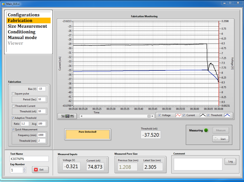
I conditioned the pore and enlarged it to 7.3-nm in the hopes of an easy DNA experiment. It retified quite a bit initially, which is usually a bad sign for DNA, so I left it overnight to clean up.
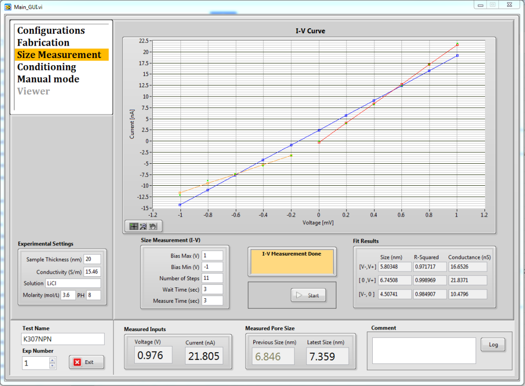
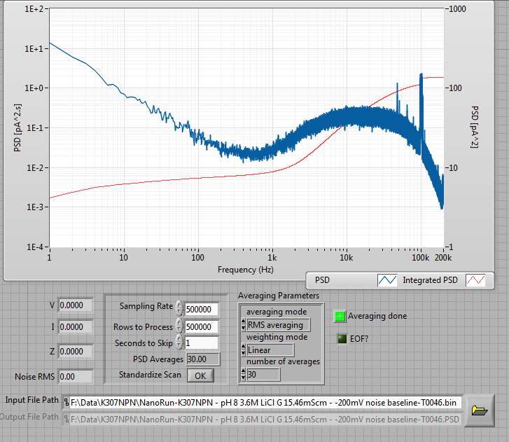
The next morning the IV and PSD were both quite clean (surprisingly so, for a chip this large – I would have expected extra noise from the capacitance but in reality it is only about 50% high noise peak-to-peak than our usual smaller chips). The PSD here is done at -200mV, which is the usual standard we use to characterize our pores. Generally a value of less than 10 pA^2/Hz at 1Hz means a good enough pore for DNA. This PSD could easily have been for a regular membrane, the NPN is electrically invisible here, which doesn’t bode well.
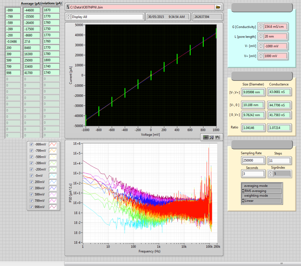
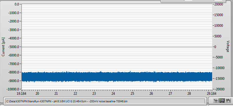
The initial baseline current before addition of DNA:
After addition of 5kbp dsDNA fragments, no events were observed, but the baseline shifted, indicating wither a clog or a partial blockage of the pore.
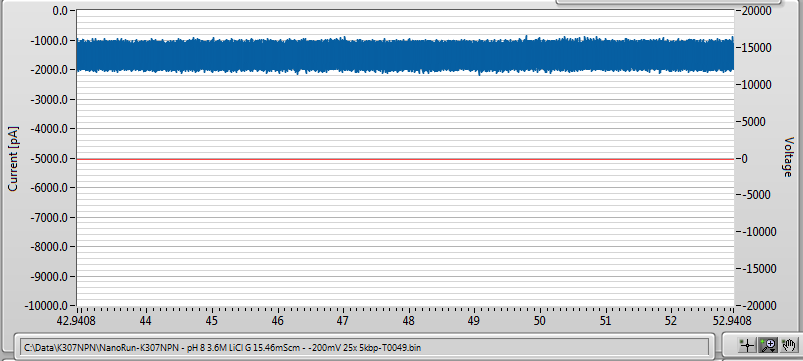
Interestingly, the noise is almost unchanged in the new baseline. Usually with a clog it gets at least a little bit noisier. I wondered at this point if some of the NPN might have broken off and fallen into the hole that had the pore in it, clogging it or making it harder for fluid to access.On a hunch, I flushed out the trans side of the flow cell with buffer, and the baseline recovered very slightly and got a little noisier:
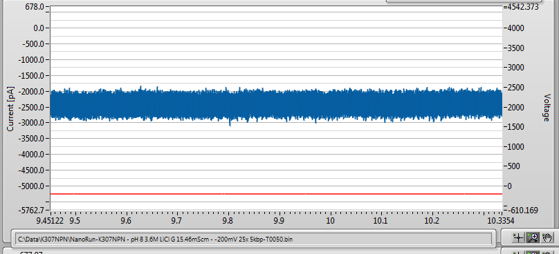
I then flushed out the cis side as well, getting slightly more recovery, and slightly less noise.
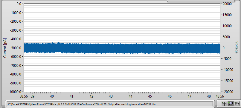
I am not entirely sure yet what to make of this. However, this could be a weakness of the holes design of the oxide layer over the posts design. Because we will only make a single pore in a single hole, if for some reason the NPN above that hole breaks or the hole gets clogged, the entire chip is rendered useless. With posts that are tightly arranged so as to not allow lamination between them, partial breakage of the NPN might not restrict access to the pore, though whether or not the device would still be useful in that case is not clear.
This is actually the second time I have seen this baseline-lowering behavior. The first was when I made a pore in a chip without the NPN tent just to make sure I could in the membranes you sent us. Addition of DNA in that case also simply lowered the baseline without actually causing any visible events. I am wondering if this might be due to the flow cell design. We have never used a flow cell for our experiments before, so I am unsure what flushing sample past the pore might do. It could be coincidence, as sometimes nanopore fail inexplicably, but the same failure mode twice in a row deserves some investigation.
Upon un-mounting the membrane and imaging under the microscope, it is clear that the NPN has completely delaminated (apologies for the poor image quality, I am imaging through liquid here since I didn’t want to disturb the chip by drying it off first).
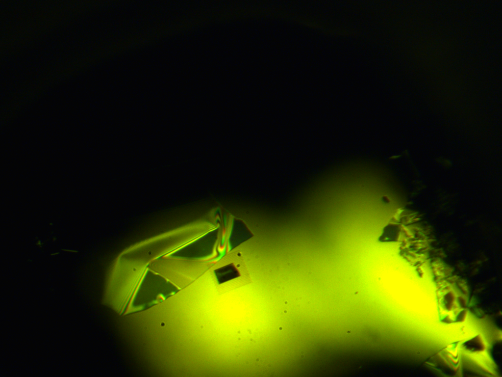
So, we are left to explain the delamination of the membrane. Your own experiments in DI water show that it is stable. The essential differences here are that I am using 3.6M LiCl, which could introduce substantial osmotic pressure across the membrane when it is initially wetted, and I am using flow across the membrane (I believe you did not? – please confirm). Some back of the envelope calculations for the rough flow rate I am using suggest that back pressure in the channel is <<1 psi, so I don’t think that could be the issue. Shear stress during flow is a possible culprit, as is transient changes in the pressure due to bubble removal during wetting of the flow cell. Osmotic pressure could be quite high, but it would be exerted downward on the membrane and so I would not expect to to contribute to delamination.
Finally, if anything I would have expected delamination of the membrane to make DNA more likely to go through the pore, if anything. So I am still leaning toward partial clogging due to a piece of the NPN breaking off and entering the hole that contains the nanopore, which might explain both results, if not how they happened.
Planned experiments:
1 – attempt to wet a membrane using salt solution instead of DI water while still under a microscope to verify that the membrane remains viable as the osmotic pressure equalizes.
2 – wet a membrane in the flow cell and immediately unmount it to see if the membrane remains viable during flow in the cell.
3 – paint PDMS up to the window after membrane transfer. This will remove extra capacitance and allow us to use capacitance as an indicator of wetting state of the inter-membrane space, while also providing additional stability to the NPN-tent assembly by pinning down the sides that might otherwise provide some leverage for shear during flow.
4 – Perform DNA experiments in the flow cell using our own chips with this form-factor to make sure that it is not the flow cell that is causing problems for DNA experiments.
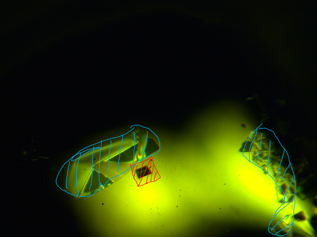
EDIT: the final image needs some more explanation. Regions cross-hatched in blue are NPN, and the red denotes the region with the posts, no longer covered with NPN.
Are you saying the membrane is delaminated just because you cannot see the membrane in the image? Or do you see where it went? Since I’ve never seen the membrane under water, I’m questioning if it might not be visible. In the same image, what are all the crystal looking features near the oxide region?
You can see the membrane in the image. That sheet in the upper left and on the chips on the right side are all NPN (what you called the crystal-looking feature). It just isn’t covering the free-standing region with the posts anymore, and it was before I mounted it. It also looks like it may be raised up from the chip, no longer laying flat.
I realized the image needed some more explanation so I did some horrible drawings on it and added it to the end of the post.
I can see the membrane on the left now. It looks intact and pitched. The stuff on the right still looks strange to me.
Yes, the membrane would want to collapse in high salts if it was a temporary osmotic force. The structure is so small that shear forces should be exceeding low near the surface, but there still needs to be a some affinity to the surface in order for the structure to not slip. I’m not sure what the nature of this affinity is in low salts, but I’m wondering if it is compromised in high salts.
We are away at a conference this week or we would be trying to bond the nitride to the oxide with an ozone treatment. In the meantime, your tests sound like the right ones to teach us something.
The stuff on the right is just badly fractured. That’s probably where I poked the membrane with tweezers, so it ending up chipping into small pieces and sticking like that. The stuff on the left is intact and pitched – when I say delaminated, I am referring only to the fact that the region with holes and the free-standing membrane came uncovered.
I’m wondering if my transfer process with steam between the chips might have destabilized the membrane. Water in the interface might allow the membrane to stick when in air, but when wetted it could come off. My next attempts will use steam only to seal it after transfer, not between the chips.