Nanoporous and Nonporous Tents show interesting wetting behavior
Summary
Since our last attempt, Greg and I have been attempting to refine our tenting experiments with the goal of demonstrating that we’re able to hydrate the volume underneath a nanoporous tent. This latest experiment is very similar to our previous experiment in theory, but we made some key changes which are discussed herein. Most notably, this time around we were able to isolate the signal-creating fluorophore to only the region directly under the tent, equipping us with interpretive powers which we believe have led us to an increasingly robust understanding of how these tents behave. In addition, visual characterization of surface wetting behavior of both nano- and non-porous membranes under various conditions has provided us with what we believe to be the strongest evidence to date for wetting under the tent.
The experiment is designed to provide evidence that the volume under a nanoporous tent has been wetted, by diffusion of an enzyme (calf intestinal alkaline phosphatase, ciAP) through that volume to the surface of the chip, which has been coated in the ciAP substrate (fluorescein diphosphate, FDP) via poly-L-lysine (PLL) directly under the tent only. If the enzyme is able to reach the substrate, it catalyzes a dephosphorylation reaction which results in fluorescent signal from the substrate in the FITC band.
The control for this experiment is the same procedure with a non-porous tent instead of a nanoporous one. It is important to note that the non-porous control is NOT a control for whether or not the region under the tent is wetted, as when using a non-porous tent no enzyme can access the substrate under the tent regardless of wetting. Instead, it can only demonstrate that diffusive access through the tent is necessary for a positive result.
Reagents:
- Coating solution
- 10:1 solution of FDP to PLL in DI water
- 10 uM FDP; 1 uM PLL
- Enzyme solution
- 0.08 ug/mL of ciAP in tris buffered saline (TBS)
- TBS is 50 mM tris and 150 mM NaCl, pH 7.4
- 20 uL is required for each chip
Procedure:
- Coating
- A glass micropipette is pulled with the pipette puller set to medium heat and filled with coating solution
- The micropipette is connected to a microinjector pump’s injector outport and mounted on a micromanipulator attached or adjacent to a non-inverted microscope (objective above sample)
- Themicroinjector pump is calibrated
- A piece of glass is placed under the microscope and the micropipette tip is touched to its surface in an attempt to deposit a bead of coating solution
- The “balance” knob is tweaked until the deposited bead is of appropriate size (comparable to that of the chip active area) and does not stick to the pipette tip when it is removed from the glass
- The foot pump is not used here
- The coating solution is applied to the active area (freestanding membrane and surrounding oxide pattern) of the chip to be treated and allowed to evaporate
- Tenting
- Each substrate and chip are clamped together flat side to flat side using the burst pressure clamp.
- Tenting chips are inverted over the substrate, and placed into contact
- repositioned so the active area is centered over the active area of the substrate
- Mild amount of film stress observed when chips are in contact
- Tents are punctured using sharp tweezers, pressing against one corner of thetenting chip
- ****Deviation by using glass micropipette instead of tweezers
- Chips are passed over a beaker of boiling DI water, 5 seconds
- Single color, large rectangular sheet is ideal
- Tenting chips are removed
- Inspect under microscope
- Wetting
- The substrates are all placed in the same gel box and exposed to room air for a few minutes
- Gel boxes are closed, and placed in freezer for 10 minutes (down from 15)
- Inspect gel boxes for cloud of humidity
- if no clouding is present, redo the condensation treatment by passing the gel box over boiling water, to capture humidity
- Minimize time between parts (3) and (4)
- Assay
- The chip is placed face-up onto a piece of silicone stuck to a glass slide, and 20uL of enzyme solution are pipetted onto its surface
- A glass coverslip is pressed gently down over the surface of the chip until it is flush with the chip, breaking the surface tension of the bead of enzyme solution
- The chip is placed under the fluorescence microscope, which is centered and focused on the window
- Five minutes after the enzyme solution was applied, images are taken with the Total Control MATLAB GUI using the FITC excitation lamp, taking care not to expose the samples to the excitation laser longer than necessary to avoid photobleaching
- Fluorescence is quantified using ImageJ
Departures from previous experiments:
- Instead of using breath to delaminate the membranes, the clamped chips were placed over a beaker of boiling DI water for 5 seconds. The condensation appears to be of larger size (~10 microns) than what was observed with the breathing technique (<5 microns), but tents were still transferred successfully.
- Instead of poking membranes with tweezers to create an initial tear, I used a glass micropipette with a very fine tip. This created a smaller, much more uniform tear. Highly recommended.
- In this experiment, the fluorescent substrate was applied only directly under the tent, rather than to the entire chip surface. This should enhance the contrast between experiments in which the enzyme was able to reach the active area under the tent and those in which is was not.
Nonporous Wetting
A non porous membrane should not be able to allow water into a nanocavity, or under a tented structure if perfectly sealed. Therefore, water should bead up on the surface (it does) and accumulate in capillaries if not entirely down (it does).
Fluorescent Nanoporous
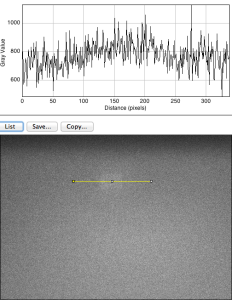
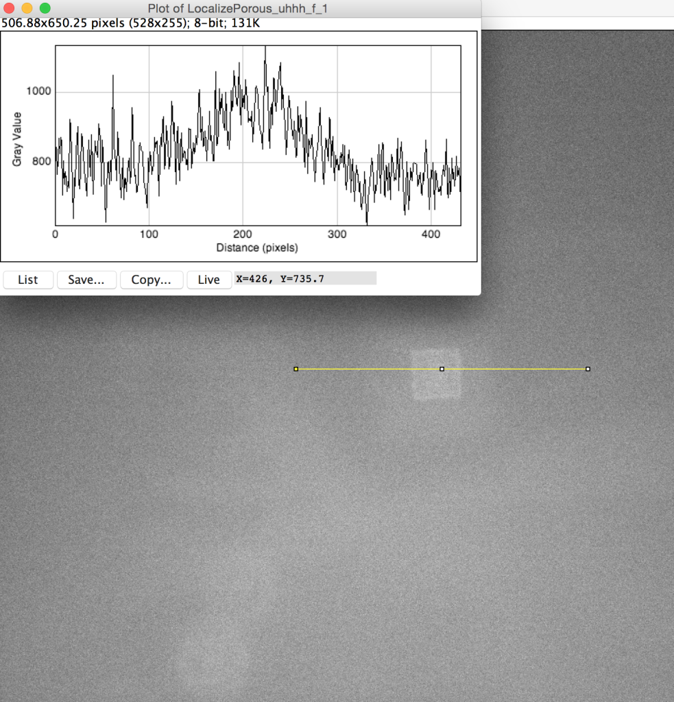
When the fluorescence experiment was performed with a nanoporous tent (right below), we observed a clear peak of signal directly at the freestanding region. Crucially, the signal does NOT fall off steeply at the border of the freestanding membrane, but rather falls of gradually, indicating that the signal observed in this image is not an artifact of increase light transmittance at the membrane but real fluorophore. Because the fluorophore is a small molecule, it diffuses readily over the short distance accounted for in this image (the membrane is roughly 50-by-50 microns,) resulting in a diffuse, low-contrast image. The left image shows a totally untreated chip, with no tent, fluorophore, or enzyme. It is noticeably dimmer with a less-defined peak and no distinguishable oxide pattern. These results are in keeping with our understanding of the behavior of the system, but a publishable version of this image would require comparison of the right image to one without the enzyme (with tent and fluorophore) as well as one without the fluorophore (with tent and enzyme,) which we have not yet collected.
|
|
|
Fluorescent Nonporous
None of the non-porous membranes tented perfectly. Microscopic wrinkles were apparent on all chips. These images show fluorophore everywhere around the active area, indicating that there is fluidic connection outside the tent, allowing the enzyme to come into the active area. Unlike the nanoporous tent, the fluorophore cannot diffuse through the nonporous tent, and instead diffuses along the fluidically connected regions (gif). It’s a like an angiogram. One of the capillaries actually appears pinched off during the 30 minute timelapse.
 |
 |
Over these small observation distances (sub 300 nm), we wouldn’t expect to see a sharp concentration change. The contrast in the right image is due to more fluorophore being present in the wells (bright circles), than existing in the layer between the tent and the oxide. The brightness in the image is indicative of water depth. The bright signal in the center is due to extra transmitted light in the freestanding region.
The gif is a 30 minute timelapse image, under a nonporous tent. Fluorophore diffuses through these nanocapillaries away from the source of the reaction.
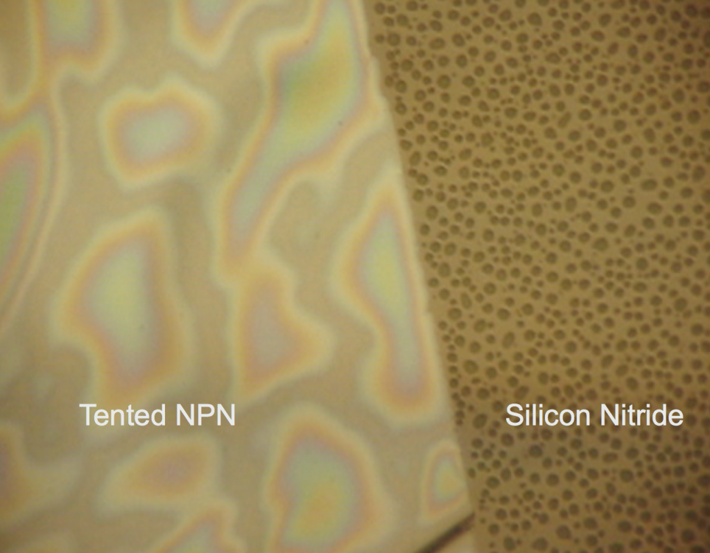
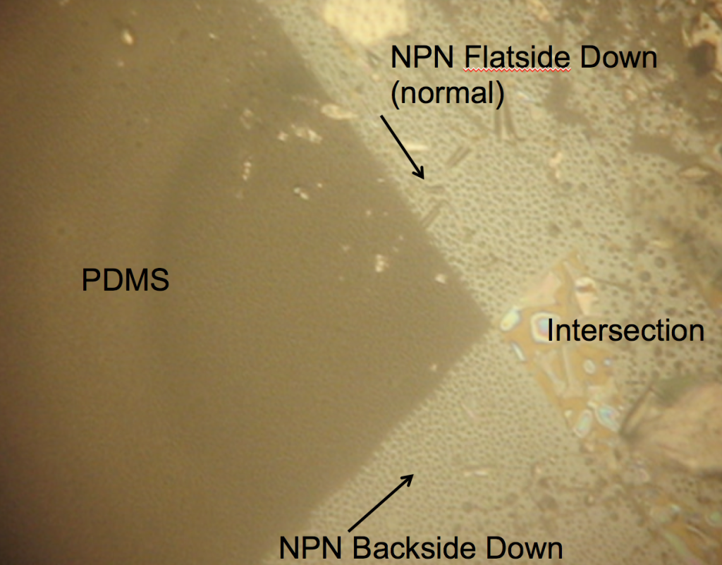
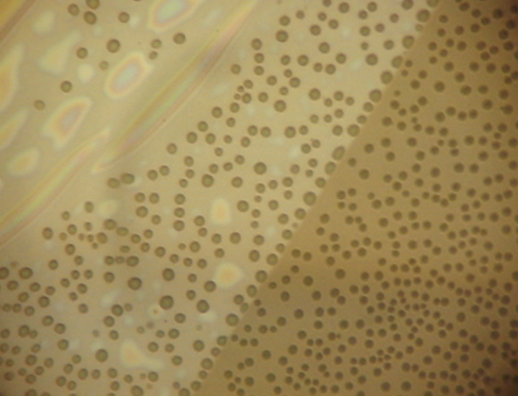
Wetting behavior of NPN material
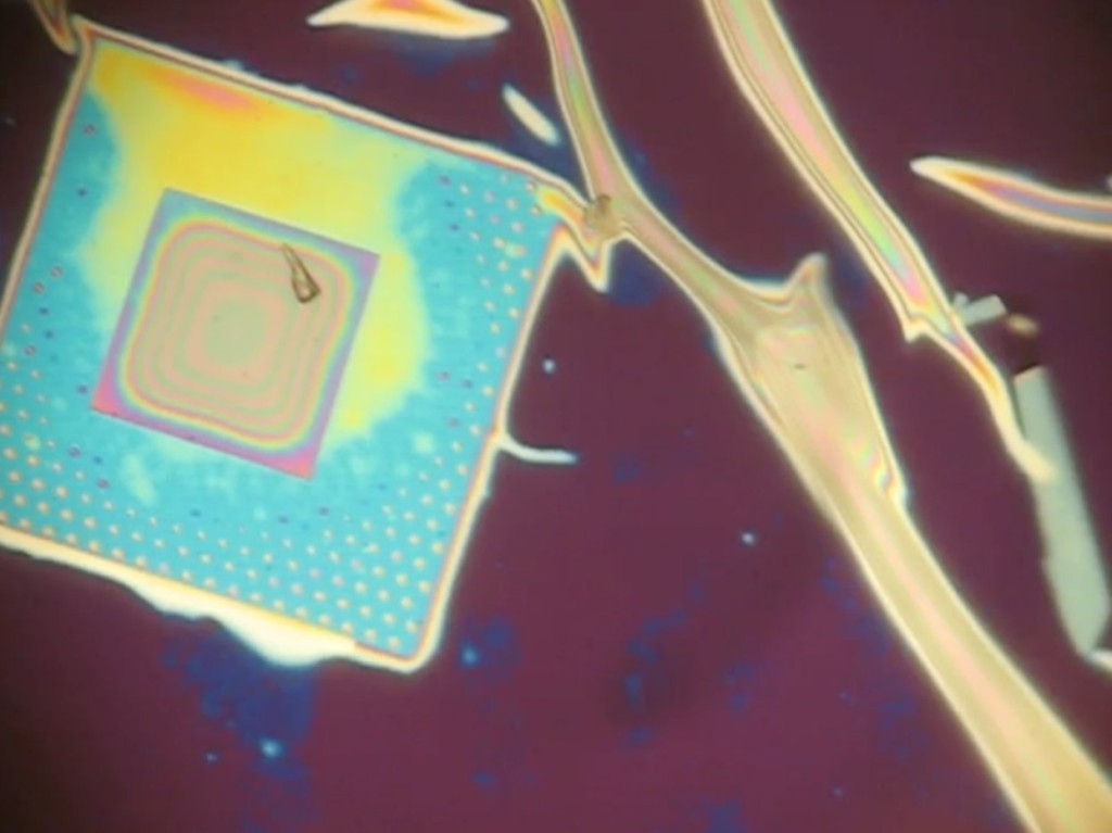
Dry 1085 NPN nanomembranes (tents are wet by virtue of fabrication) were smashed against PDMS (flatside down and backside down) to see if there were different wetting properties of the surfaces of the freestanding nanomembrane. I was expecting the rainbow behavior shown in the first image to be on both membrane surfaces if the nanoporous texture was responsible for the interesting wetting. However, both nanomembrane surfaces show hydrophobicity! I placed down both of these membranes dry, so the wet deposition of the tents is probably playing a role in the interesting wetting behavior.
To determine how essential the wet delamination process is to creating the hydrophillic sheeting of water, we first made the nanoporous membrane hydrophillic by breathing on it repeatedly (glass substrate). The idea is that water vapor makes it under the tent from the nanopores and condenses. When the membrane is heated over a short time, the water evaporates, but incompletely, priming the surface for easier wetting the next time.
After dessication in the 70C oven for 20 minutes, we believed any residual water under the tent would be completely removed, and the surface would again be hydrophobic
Further breathing on the substrate (repeated wetting and incomplete drying) would turn the surface apparently hydrophillic again.
From these videos, we concluded that the water is getting underneath the tent, from residual wetness where the tent appears to be in contact with the surface. We then asked the question if the membrane would float away, if left in DI over night (it does not).
Conclusions
1. Water is getting underneath the tent when we vapor prime (breathing or boiling water) the surface
2. Nonporous materials are more difficult to tent evenly compared to the nanoporous materials, resulting in large macroscopic wrinkles.
3. We have stronger evidence that the tent is not completely in contact with the substrate surface, the oxide structures especially. We need to understand better the degree of contact between the tenting materials and the substrate surface.
4. More work on the nanoporous tent fluorescent signal is needed to verify our proposed mechanism of action, that the fluorophore diffuses away from the substrate through the tent, resulting in diffuse, sparse signal.
diffusion has made a mess of that fluorescence image, the SNR is rock bottom.
Something to try:
Prepare a strong aqueous solution of FITC
Tent the wells using breath method
While wetted add a drop of FITC solution to the surface – should diffuse through into the wells.
Allow to dry – whole structure should be covered in FITC (green everywhere).
Lastly, use a drop of dH2O on the thoroughly dried structure – should sit on top and not wet the wells – if this drop is then shaken off it should take the FITC from off the nanomembrane but leave the dried out stuff trapped into the wells.
Its possible the layer of dried FITC will wick the final “wash” drop into the wells anyway – in which case you’ll lose all the signal. If the wells refuse to wet then they’ll stay green and the membrane will clear up.
I looked at three suppliers’ websites last night. All said 0.5 mM to 10 mM MgCl2 is required for alkaline phosphatase activity. Your enzyme may be starving for a cofactor and may not be generating signal for you.
I think Tucker mentioned that the CAIP preparation has 0.5 mM ZnCl2 that gets diluted 100-fold in the experiments. By adding 0.5 mM MgCl2, I think you’ll increase the reaction rate by 100-fold.
You can also shut down the reaction by dropping on concentrated EDTA to chelate all the Mg2+. This would decrease the fluorescent signal over time, so you could watch the fluorescence as the signal molecule diffuses away.
The assay for standardizing alkaline phosphatase activity (i.e., defining units of enzyme activity) uses 0.5 mM MgCl2:
http://www.sigmaaldrich.com/technical-documents/protocols/biology/enzymatic-assay-of-alkaline-phosphatase-diethanolamine-assay.html
See the buffer at this company:
https://www.neb.com/products/m0290-alkaline-phosphatase-calf-intestinal-cip