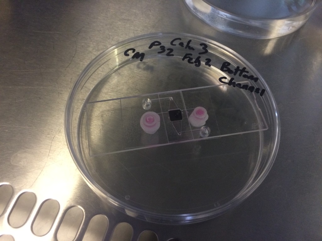
As part of my work over at the University of Nottingham, I’ve been using iBidi devices to grow cells. Eventually, I will use their product to do Raman studies of cells grown on my MgF2 substrates. I’ve been making some progress towards that end using PDMS (I’ve been using 10:1 base to curing agent for everything) to adhere coverslips to parts of the device. Orientation of the device has the large ports connect to the bottom channel (parallel to long edge of slide), and the top channel is formed by the smaller ports in an S-shape, which uses vias to move the fluid up and over the chip.
Upside down culture in an iBidi device, to allow cells to adhere to the MgF2 chip.
The general procedure is to coat PDMS on coverslips and attach them to the device, but there are a few different ways you can do that. I’ve found a combination of spin-coating thin layers of pdms and manual application is working best for me. Ideally I would like to spin coat all the layers, and not do manual application, but there are some technical limitations, due to the sizes of the coverglasses needed.
Manually coat the top surface of the ibidi device and adhere the 10×24 mm coverglass.
Manually rub the inner square of the iBidi device (with a pipette tip) and adhere the substrate chip
Spincoat the 40×24 mm coverglass to desired thickness and adhere to bottom
Cure for 4 hrs at 50 C (though solidification is apparent at 1 hr)
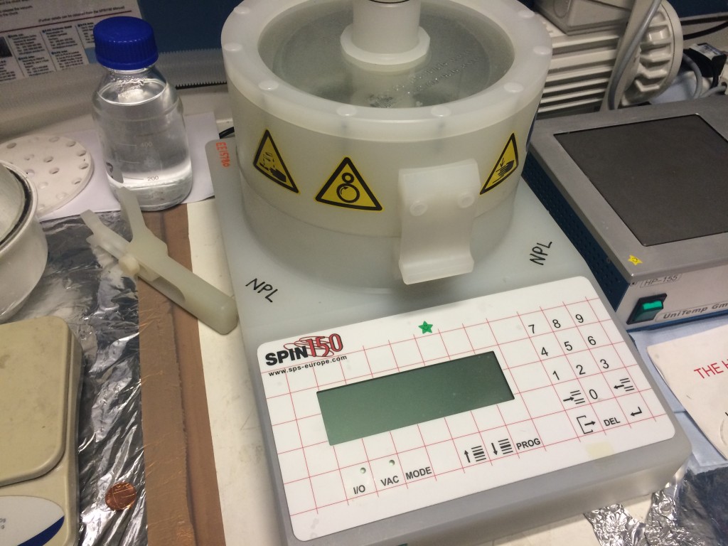
Spin coater used to apply all of my coatings. It can do 4″ wafers down to microscope slides and minimally 20mmx20mm coverglasses without compromising the device. I apply a few drops to a coverslide, or coat the entire surface of a microscope slide and immediately begin the program (500rpm for 10 s before accelerating to 3000 rpm for 120 s will give a sheer film).
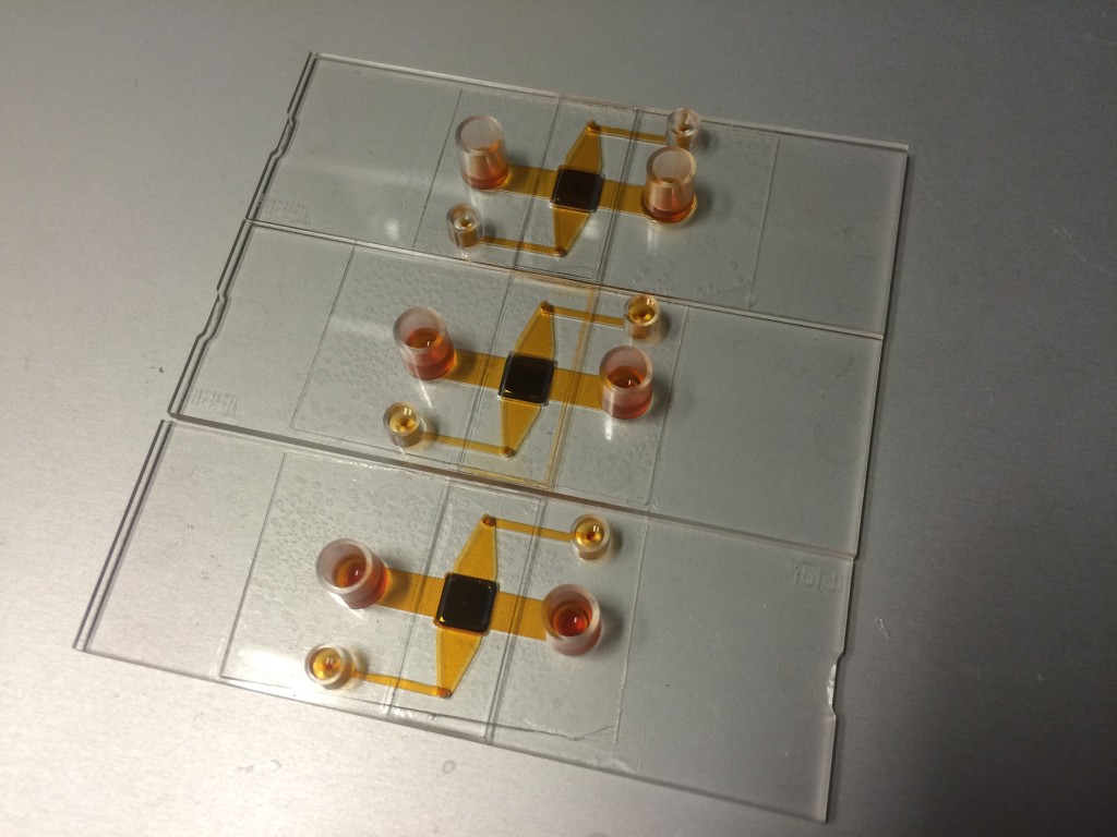
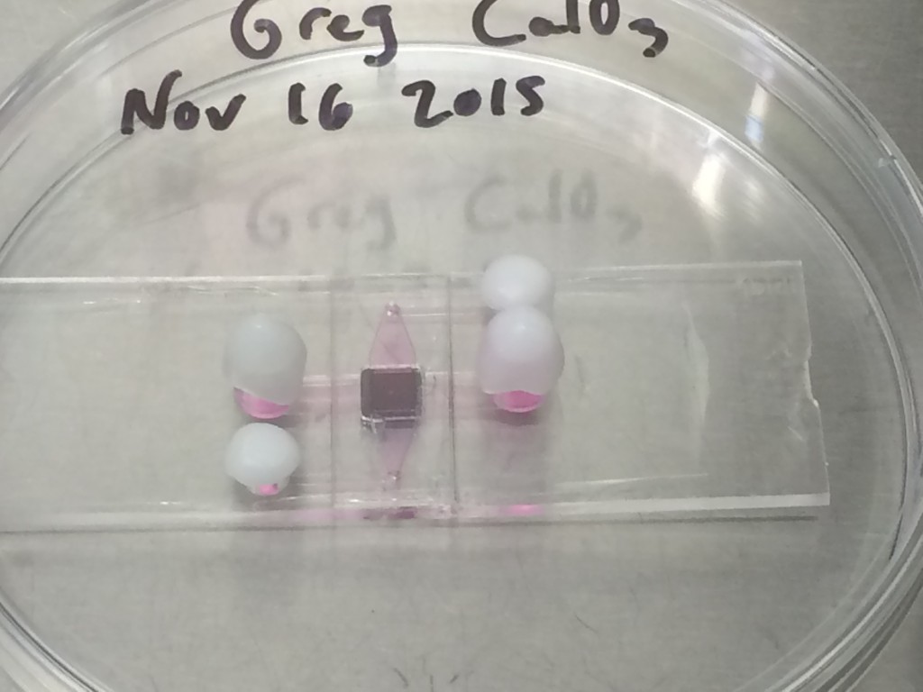
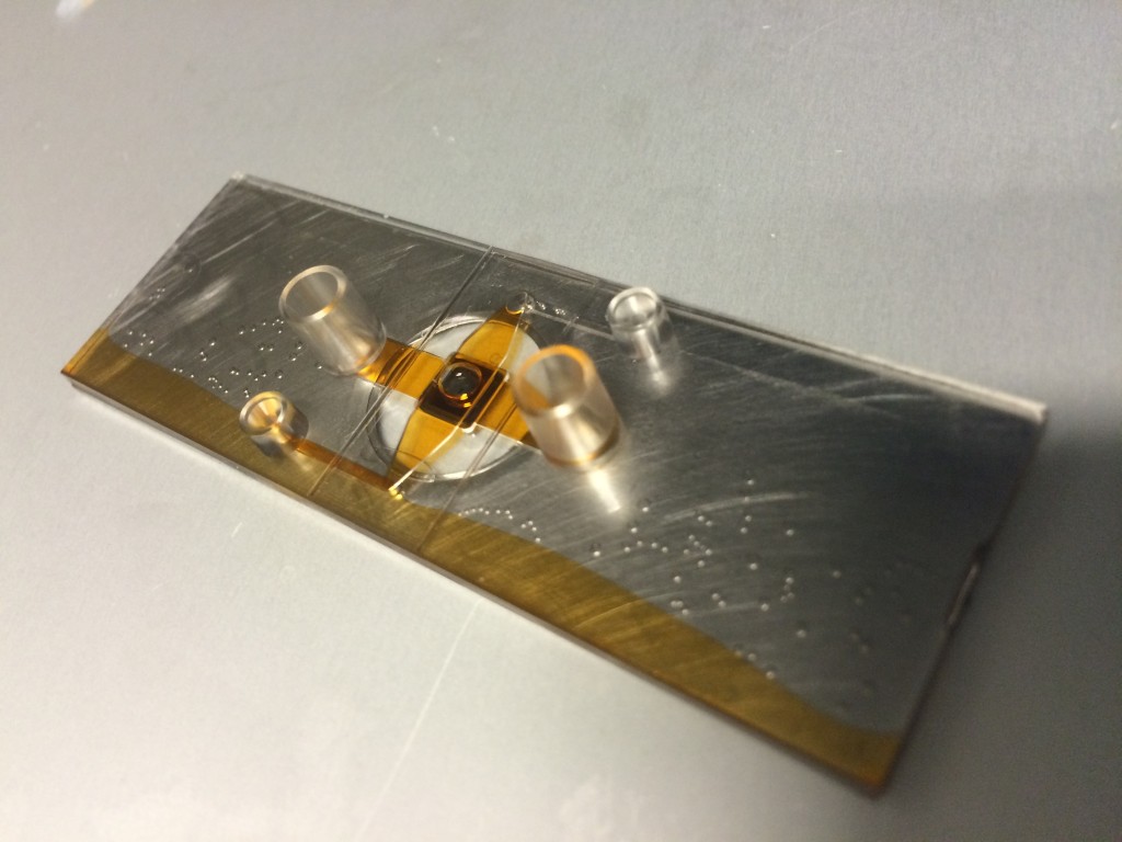
Fabricated spincoated devices. Bubbles are present even though previously degassed, due to spin coating (it’s a wonderful aerator). This property can be compensated by spin coating thicker layers, or lowering the viscosity of the PDMS and spinning slower. The middle device is leaking from the top coverslip (pdms applied manually), but the other two devices are sealed well. Note that the PDMS is everywhere on the bottom coverglass, even the floor of the channels.
The sealing method is working fine, but there are a few tricky parts that I still must overcome in order to make a Raman compatible system. First, there can be no PDMS in the observation path at all. Second, I have to integrate to a multi-height surface; that is not completely planar. Third, the MgF2 coverglass is very fragile and cannot withstand the pressure of spin coating. My strategy so far has been to tape the edges of the Raman coverslip carrier to a microscope slide, where the slide can handle the stresses of spin coating. This mitigates the third problem, but it’s not enough.
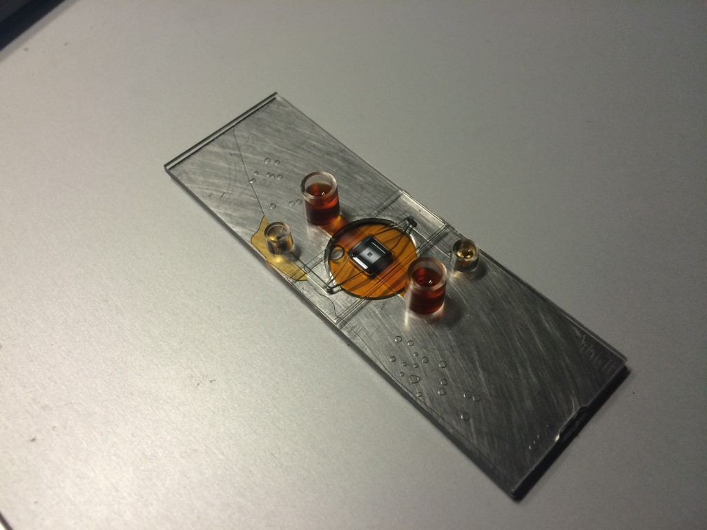
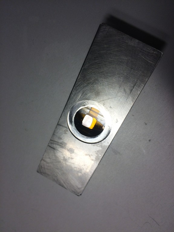
iBidi to Glass Floor bonding. The PDMS was spin coated at 1000 RPM for 100 s, cured for 1 hr at 50C on a hotplate. This thickness was enough to close off the top channel. The PDMS bonding between the brushed metal and the plastic appears good. The liquid pools underneath instead of staying in the bottom channel due to the recession of the coverslip. It remains unknown how the MgF2 will bond at this point, but it should have sufficient contact area to prevent this flooding.
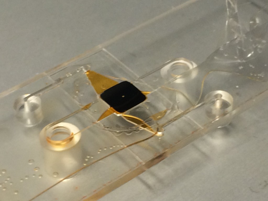
This picture demonstrates the first two problems. Because the height is multilevel, the coverslip creates a small opening beneath the bottom channel and fluid pools instead of channeling to the outport. In order to bond more of the surface to compensate, I have to use more PDMS, which blocked the top channel, coating the observation bottom channel as well. The real MgF2 coverslip will not have as much of a gap, but the problem may arise again. I plan to attack this problem by manufacturing a relief mold of the channels and sticking them to the substrate before spin coating, preventing the liquid PDMS from touching those surfaces. This will necessitate additional alignment, but ultimately, will facilitate our purpose without resorting to photolithography and dissolving toxic photoresist+developer in the channels.
By using a iBidi devices channels as a mold, we create negatives that stick to surfaces but are removable. While they must be aligned on the target substrate, they will allow us to preferentially coat PDMS everywhere but the channel regions using the spin coater, then remove the mask to expose open areas of MgF2, ready for Raman microscopy.
Things not to do
Although tempting to test out idea, flash curing (125-150 C) thin sheets of pdms in a device tends to warp the structures around it.
Curing at a higher temperature causes the iBidi plastic to deform. I was initially concerned about the thermal penetration to cure the film, but there is not a lot of PDMS volume, so it doesn’t matter for our purposes.
Update Feb 6 2016
Tape and a plastic petri dish allows me to spin coat the thinner 10x24mm coverglasses that I had to apply by hand previously.
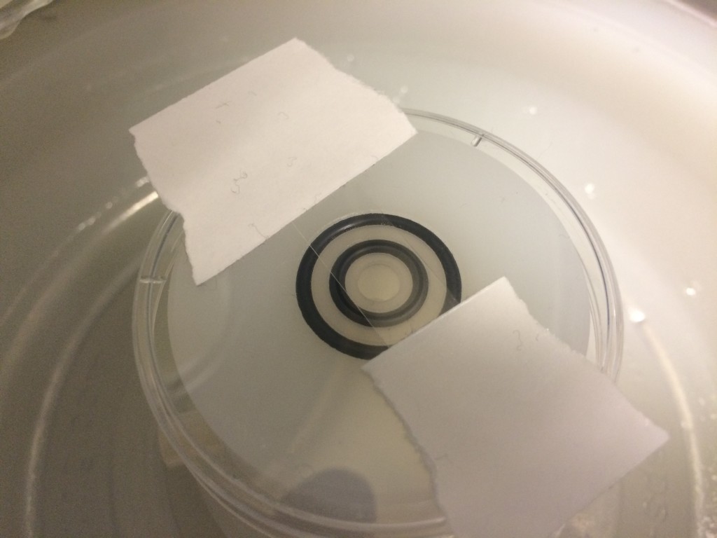
Spin coating the MgF2 coverslip is tricky because the coverslip cannot bear any of the vacuum stresses of coating; it is too fragile. So I taped the holder+coverslip to a glass slide. The piece of silicone in the middle is to prevent the observation region from being coated with PDMS.
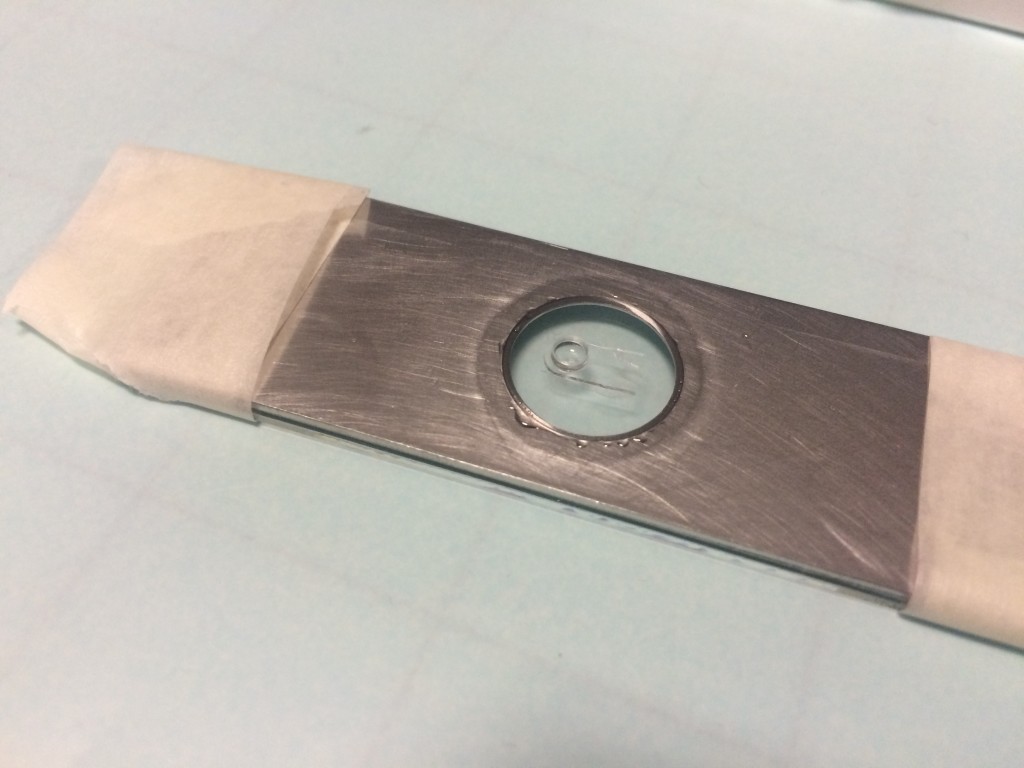
After the PDMS has been coated, the silicone mask was removed, and you can see the non coated part of the observation region on the MgF2. It was not perfect, some sheeting appears to occur, but I think I will use a higher quality mask next time with better adherence to the MgF2.
Failure, but still an improvement. PDMS still blocks off a top channel, there are some uneven coatings, but the bottom channel is successful at holding it’s shape. The height disparity between the coverglass and the metal holder has been bridged.
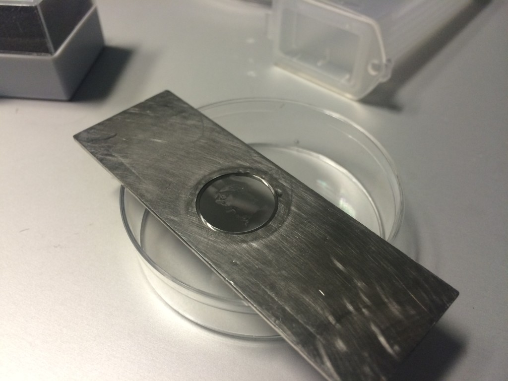
Slow curing the PDMS apparently allowed the chip to fall out of the Ibidi holder and fuse to the bottom channel. Alas no testing for this device.
Salvaging the device is very difficult because of the amount of contact area between the brittle coverglass and the PDMS. The circular coverglass is shown here to be bonded very closely to the iBidi device, too closely. Simply shearing the device won’t cut it.
In the soon to be submitted paper on diffusion models, we list two contributions to membrane resistance. The first is due to the steric and frictional hindrance a molecule encounters as it enters and diffuses through a pore (Renkin, Deen). The second is due to the time that it takes for the molecule to diffuse…
Introduction: Fibroblasts: Dermal fibroblasts are cells within the dermis layer of skin which are responsible for generating connective tissue and allowing the skin to recover from injury. A fibroblast is a type of biological cell that synthesizes the extracellular matrix and collagen, produces the structural framework (stroma) for animal tissues, and plays a critical role in wound healing. Fibroblasts are…
Last week, I ran a few experiments to see how certain membrane conditions affected the transport of fluoroscein. The first experiment presented here contained three sepcons: one with 3 pinholes, one with only 1 intact slit, and another without slits to use for the background. The controls were HBSS and fluoroscein. The sepcon with 1…
UPDATE: A look at long and short crystal dimensions (9/1/10): DLS vs. Crystal Sizes – Newest version 8/30/10 Here is a comparison of sieving curves using DLS or estimated crystal dimensions of proteins. DLS: 24 hours sieving curve. 48 hours sieving curve. Estimated longest crystal dimension: 24 hours sieving curve. 48 hours sieving curve.
In early May, the Barcikowski lab shipped us four samples of gold nanoparticles for us to run separations on. They took forever to get here, and had aggregated and precipitated by the time they arrived. About a week ago, the lab sent another batch of four samples (which differed slightly from the samples they sent…
In this post I show the sieving coefficients of simulations with a thin membrane, a thick membrane, or a no membrane case as they approach equilibrium. The simulations were carried out for 48 hours, and plotted for 1 hour time points. Both thin and thick membrane had the same pore distribution – monodisperse 10 nm…
In case you are seeking alternatives for making the cell culture device using the ibidi slide, you can try using the biocompatible double-sided adhesive tape to stick the magnesium slides to the top and bottom of the ibidi slide. You can customize the tape dimensions using the Silhouette cutter.
As for sticking the membrane chip to the slide, you can use semi-cured PDMS (for example, 1 mL of 1:10 PDMS in a 75C oven for 4 min in a 35mm petridish). The semi-cured PDMS is much more viscose so it would not flow to cover your membrane when you bake to cure the PDMS. You can dip the 4 sides of the membrane chip to get a nice PDMS coverage around the rim of the chip (if it worked out alright you will probably get ~1mm of PDMS on each side. Since our chip is ~5.4mm x 5.4mm we should be safe from PDMS spill onto the membrane itself). After dropping the chip into the ibidi slide, you can apply more semi-cured PDMS as need, but i think that’s not necessary as long as the 4 side dip is done well enough.

Hi Greg,
In case you are seeking alternatives for making the cell culture device using the ibidi slide, you can try using the biocompatible double-sided adhesive tape to stick the magnesium slides to the top and bottom of the ibidi slide. You can customize the tape dimensions using the Silhouette cutter.
3M biocompatible double-sided adhesive tape:
http://solutions.3m.com/wps/portal/3M/en_US/Medical-Devices-NA/Home/Products/Product-Catalog/~/3M-1522-Transparent-Polyethylene-Double-Sided-Medical-Tape-80-Liner?N=5006381+4294834237&rt=d
As for sticking the membrane chip to the slide, you can use semi-cured PDMS (for example, 1 mL of 1:10 PDMS in a 75C oven for 4 min in a 35mm petridish). The semi-cured PDMS is much more viscose so it would not flow to cover your membrane when you bake to cure the PDMS. You can dip the 4 sides of the membrane chip to get a nice PDMS coverage around the rim of the chip (if it worked out alright you will probably get ~1mm of PDMS on each side. Since our chip is ~5.4mm x 5.4mm we should be safe from PDMS spill onto the membrane itself). After dropping the chip into the ibidi slide, you can apply more semi-cured PDMS as need, but i think that’s not necessary as long as the 4 side dip is done well enough.
Good Luck!
Henry