Transwells interfere with Tecan measurements
This week, Christine and I have been trying to figure out if we can measure transport in the Tecan with the transwell inserts remaining within the 24-well plates. Here is a schematic of our idea (with sodium fluorescein, Na-F, as the model fluorescent molecule for transport studies):
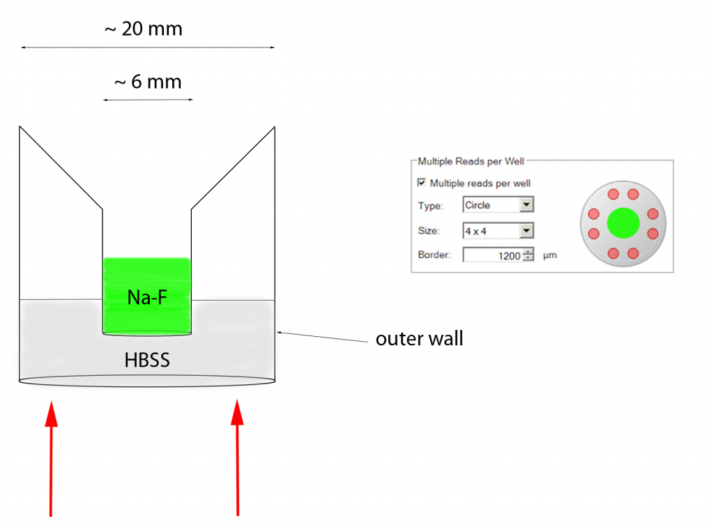
The left image is a side view, the right image, a bottom view. The transwell “upper well” is ~ 6 mm in diameter and the 24-well “lower well” is ~ 20 mm in diameter. The beam diameter in the Tecan is 2 mm, 3 mm and 0.7 mm for bottom, top and absorbance readings, respectively (the red arrows). Therefore, it might be possible to gather absorbance/ fluorescence data from the lower well without interference from the upper well because there is an ~ 6 mm ring between the outer well wall and the transwell. However, it’s also possible that light diffraction from the 24-well plastic lower well might excite the Na-F in the upper well and contribute to the fluorescence/absorbance reading. We were also unsure of edge effects from the 24-well lower well.
We found that there is too much interference to make absorbance and fluorescence measurements with the transwells in the 24-well plates.
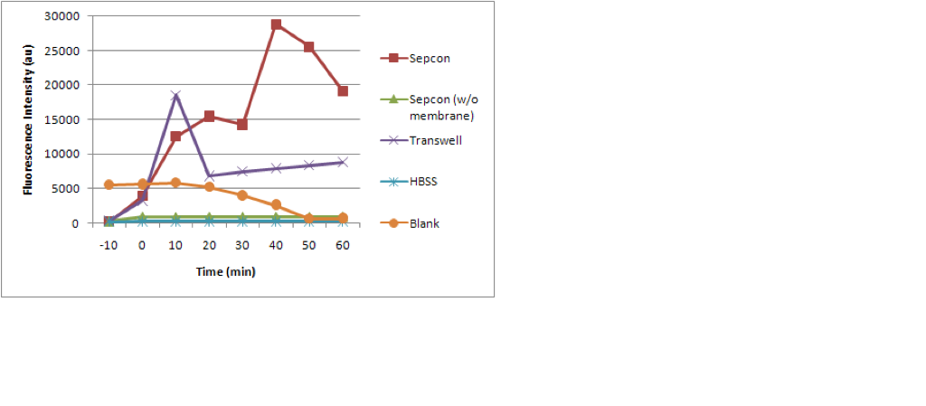
The first evidence came in Christine’s post (here), in which the fluorescence increased dramatically after the addition of sodium fluorescein into transwells and Sepcon transwells (from time = -10 minutes to time = 0 minutes, where Na-F was added at time = -1 minute). Blank fluorescence was steady over this timeframe.
I did a number of plate scans to try to map the location of transwell inserts in 24-well plates and found considerable absorbance/fluorescent signals from the walls and the transwell. I first did a 600nm ABS scan with a 15×15 filled circle scan with a 1000um border and compared it to a 15×15 open circle (see above) with a 1000 um border. The “border” is the radial distance from the well wall from which the measurement begins. The left well contains a Corning transwell with HBSS and the right well just contains HBSS:
Filled circle:
![]()
Open circle:
![]()
In both of these scans, the 24-well outer wall is clearly absorbing light. The transwell is clearly visible in the filled circle scan but not the open circle. To try to decrease the absorbance by the outer well, I repeated these scans with a 2000 um border:
Filled circle:
![]()
Open circle:
![]()
With this larger border, the outer wall absorbance is effectively eliminated. The transwell absorbance dominates the filled circle scan. However the absorbance in the open circle scan of the transwell well is much higher than that of the 1000 um border open circle scan. This indicates that the transwell is now contributing to the absorbance signal. This suggests that we should be using ~ 2000 um border for absorbace measurements in BD Falcon 24-well plates.
I then pushed the border out to 50 um and did a filled circle scan:
![]()
In the blank well, the wall absorbance is clearly visible. In the transwell well, you can distinguish the wall absorbance from the transwell absorbance. Unfortunately, there is no ring of very low absorbance between the wall and the transwell even though there is ~ 6 mm of space between these features. Therefore, it is not possible to measure the transport of molecules from transwells into the lower wells of 24-well plates while keeping the transwells in the multiwell plates IN ABSORBANCE MODE. Although all of this data is from 600 nm absorbance, I would expect similar (if not worse) results from fluorescence scans since polystyrene autfluoresces more than it absorbs.