A Power-free Pneumatic System for Controlling Fluid Flow
Introduction
When searching for a flow control system for microfluidic cell culture, we look to balance the ease of use, accessibility, and precision of fluidic control. For instance, researchers have explored different powered actuation methods for miniaturized precise proportional fluid control. These actuation methods include electromechanical, electrostatic, electromagnetic, piezoelectric, and thermal-based. The necessary power sources, design-specific fabrication processes, along with the associated complexities and costs make these devices challenging to be widely implemented. On the other end of the spectrum, researchers explore passive mechanisms to realize portable and user-friendly fluidic driving. Capillary-force-based, built-in-pressure-driven, and gravity-driven are among the most common passive pumping mechanisms designated for microfluidic platforms. Despite the lower costs and ease of use, passive pumping mechanisms are usually designated for applications tolerant to flow instabilities as they often lack control over the fluid driving rates. Moreover, capillary-force-based devices generally suffer from backflows; gravity-driven and typical built-in-pneumatic-pressured pumps exhibit descending flow rates during pumping. These limitations make them unsuitable for long-term usage that requires continuous perfusion. Since attaining precise control of fluidic driving pressure enables proportionally-controlled liquid flow rates applicable for a variety of fluidic applications, i.e. microfluidic cell culture, we look to create an accessible, power-free, miniature system with low-complexity fabrication processes while possessing tunable fluidic control capability. Here, we introduce a simple and accessible pneumatic pumping platform consisted of a 3D-printed refillable air tank, two stages of micro pressure regulator (µPR) to provide a tunable ∆P that controls the flow rate in a microfluidic channel network, a liquid reservoir for cell media, and the m-µSiM culture platform. Pneumatic pumping schemes create a defined pressure drop (∆P) across microfluidic networks to drive fluid flows. The flow rate is governed by the hydraulic analogy to Ohm’s Law, Q=∆P∙R-1, where R is the hydrodynamic resistance of the network. As in vitro studies have shown that cells distinctly change in morphology (aligned and more resembling the in vivo status as compared to static cultures) when exposed to mechanical stimuli, we plan to create a benchtop tunable pumping platform with different stimuli levels for microfluidic perfusion culture. Having a standalone, power-free flow control platform allows researchers to easily move the perfusion culture system in and out of incubators without dealing with the power-cord wiring complications. We plan to demonstrate the tunability by performing microfluidic cell culture of endothelial cells (HUVECs) in two modes: (1) proliferation and (2) alignment of the cells.
Theory
How the pump works
a) Force-Balance Mechanism to Regulate Outlet Pressure
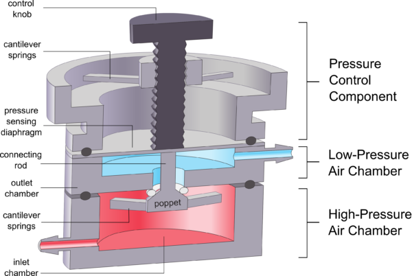
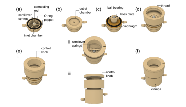
Pressure regulators are commonly used in pneumatic circuits to reduce high-pressure air to a lower, controllable pressure setpoint for downstream applications. As with most manual pressure regulators, the 3D-printed µPR uses a force-balance mechanism and is designed to maintain a user-defined setpoint suitable for standard microfluidic systems (~1-10kPa). As shown in Figure 1, the µPR consists of a high-pressure air chamber, low-pressure air chamber, and pressure control component. The high-pressure air chamber includes the closing (bottom) cantilever springs, the poppet valve, and the connecting rod. This chamber receives constant pressure from a miniature air compressor. The low-pressure chamber with the pressure sensing diaphragm outputs the regulated outlet pressure. The pressure control component consists of 3D-printed top cantilever springs and the control knob, which is used to control the outlet pressure as described below.
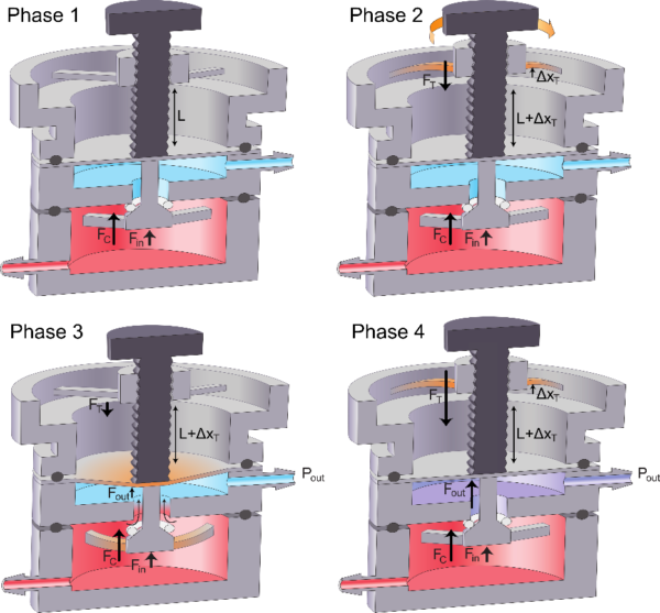
b) Operating phases of the pressure regulator
c) Power-free system with a refillable air tank

The workflow of the power-free cell culture system is described below.
- The 3D-printed air tank is pressurized with a barbed fitting through the refill port.
- The 3D-printed air tank provides high-pressure (100-200 kPa) air to the 1st stage pressure regulator.
- The 1st stage regulates the high-pressure to an intermediate pressure range (40-60 kPa)
- The outlet of the 1st stage supplies the inlet of the 2nd stage.
- The 2nd stage regulates the intermediate pressure (40-60 kPa) to the desired output pressure range (0.5-5 kPa)
- The output of the 2nd stage is connected to pressurize a liquid reservoir filled with cell media.
- The output of the liquid reservoir is connected to the stabilizing microchannel.
- The output of the stabilizing microchannel is connected to the m-µSiM cell culture platform.
Materials and Methods
Device fabrication
i). Pressurized mini air tank
We 3D-printed the miniaturized air tank. We pressurize the air tank to 200 kPa with a Dwyer-110 pressure gauge and a ControlAir Type-90 regulator. We then connect the device with a Honeywell pressure sensor (TBPDANS030PGUCV, Honeywell International Inc., Charlotte, NC, USA) to monitor the pressure in the air tank for 24 hours. We would adjust the required wall thickness of the mini air tank until we don’t see pressure loss for the 24-hour test.
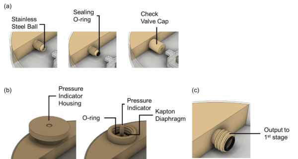
Some features we designed in this setup include a check-valve refill port, a pressure indicator and a screw-on output channel to the 1st-stage regulator
ii). Dual-stage pressure regulator
1st stage
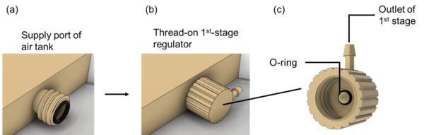
The major components of the 1st-stage regulator are shown in Figure 5. The outlet chamber is 3D-printed with the surgical guide resin (Formlabs, Somerville, MA) as the diaphragm material, connection rod, and poppet valve. We manually expand a size 002 O-ring to and fit in the gap between the poppet valve and the outlet chamber as shown in Figure 5. We thread on the 1st-stage regulator to the supply port of the air tank.
2nd stage:
The optimized 2nd stage of the pressure regulator is fabricated as shown in Figure 6.
Results and Discussion
Air Tank Sealing
The 3D-printed air tank was able to maintain the 200 kPa pressure filled with ControlAir Type-90 pressure regulator for 72 hours.
Future Experiments
a) Supply Pressure Effect
The supply pressure effect would be tested with cascaded stages of the pressure regulator. We supply pressure to the inlet of the 2nd stage using the Dwyer-110 pressure gauge and Control Air Type-90 regulator. The outlet of the 2nd stage would be connected to a Honeywell pressure sensor suitable for pressures from 0 to 35 kPa (TBPDANS005PGUCV). We supply inlet pressure to the pressure regulator at 200 kPa and tune the control knob to output 0.5, 2.5, and 5 kPa, to represent the low, medium, and high setpoints of the output range. We would then reduce the supply pressure by 10 kPa decrements from 200 kPa to 100 kPa meanwhile monitoring the output pressures.
b) Pressure and Flow Rate Measurement
The general pressure/flow experimental setup features the pressure regulator and the PDMS stabilizing microchannel (60-µm height, 200-µm width, and 7-cm length). We supply pressure to the 1st stage pressure regulator with a compressed air chamber with 200 kPa gauge pressure. The outlet of the 1st stage regulator is connected to supply the inlet of the 2nd-stage pressure regulator. We tune the 1st stage device such that the 1st stage would output pressures ranging from 40 to 60 kPa. The outlet of the 2nd stage was then connected to a three-way connector, with one end feeding the inlet of the PDMS microfluidic channel and the other connected to a Honeywell pressure sensor (TBPDANS005PGUCV, Honeywell International Inc., Charlotte, NC, USA). Silicone tubings (2-mm ID, 5-cm length) were used to connect these components. The PDMS microchannel was primed with a solution of blue dye (McCormick Inc., Baltimore, MD, USA) in deionized water to improve contrast.
c) Characterization of outlet pressure vs control knob position
The aforementioned experimental setup allowed the characterization of based on the rotational positions of the control knob. We characterize the device when supplied with a constant 200 kPa to the 1st stage regulator. The outlet of the 1st stage regulator’s pressure is documented over 24 hours with the Honeywell pressure sensor for 0 to 200 kPa. We would connect the 1st-stage regulator’s outlet to supply the inlet of the 2nd-stage regulator. A full cycle of the calibration process included clockwise rotational turns ( increased from 0.5 to 5 kPa) and counter-clockwise turns ( decreased from 5 to 0.5 kPa).
d) Cell culture on the m-uSiM platform
We turn the control knob of the 2nd stage of the pressure regulator to the calibrated results obtained from section (b) to output 2.5 kPa for delivering cell media to the m-uSiM culture platform, and 5 kPa to deliver flow to align the cells. We look to demonstrate the device with HUVECs. We would look into the coefficients of alignment (CoA), directions of the cells within ±15º. The 2.5 kPa-driven cell media flow should result in CoA of cells under 0.50 while forming confluent HUVEC monolayer after 24 hours of cell media perfusion. The 5-kPa driven flow should yield CoA greater than 0.50, which indicates successful alignment of HUVECs under the shear stresses created via our power-free flow control system.
The pressure regulator presented in Figure 1 and 2 are published here:
https://www.nature.com/articles/s41598-022-15087-9