Mark Lifson's Lab Rotation
The goal of this rotation was to create a device to test the electro-osmotic properties of the membrane bound silicon chips. To perform this task, it was necessary to attach two glass pipettes onto both sides of a chip. The method required that the protocol be repeatable and easy to perform. Although it appears to be a simple problem, it is in fact more complex because of the small sizes involved. In this ten week rotation various experiments were performed with a variety of results. Short-term solutions were found allowing for a framework to test the various electro-osmotic properties. However, long term solutions must still be investigated if these devices area to be used in potential applications.
Experiment 1:
For a first pass, a glass coverslip box was drilled using a hematocrit capillary sized drill bit. The alignment drawn on the box allowed for a glass pipette to be suspended such that filling the box with PDMS would create a mold of the pipette within the coverslip box. The idea was then to push the pipette out of the mold creating a straight track so that two new pipettes could be placed onto the track on either side of the mold. The TEM chip would then be inserted through the center of the mold and the insertion point filled to create a completely sealed system. However, there were numerous design issues, namely: extracting the glass pipette from the mold, aligning the chip into the PDMS block such that the window would be on the same line as both pipettes, and the requirement for a large amount of PDMS per device. In the face of these problems, the positioning of the chip appeared to be the most difficult and there was no way to ensure that the filling fluid wouldn’t escape around the boundaries of the chip.
Experiment 2:
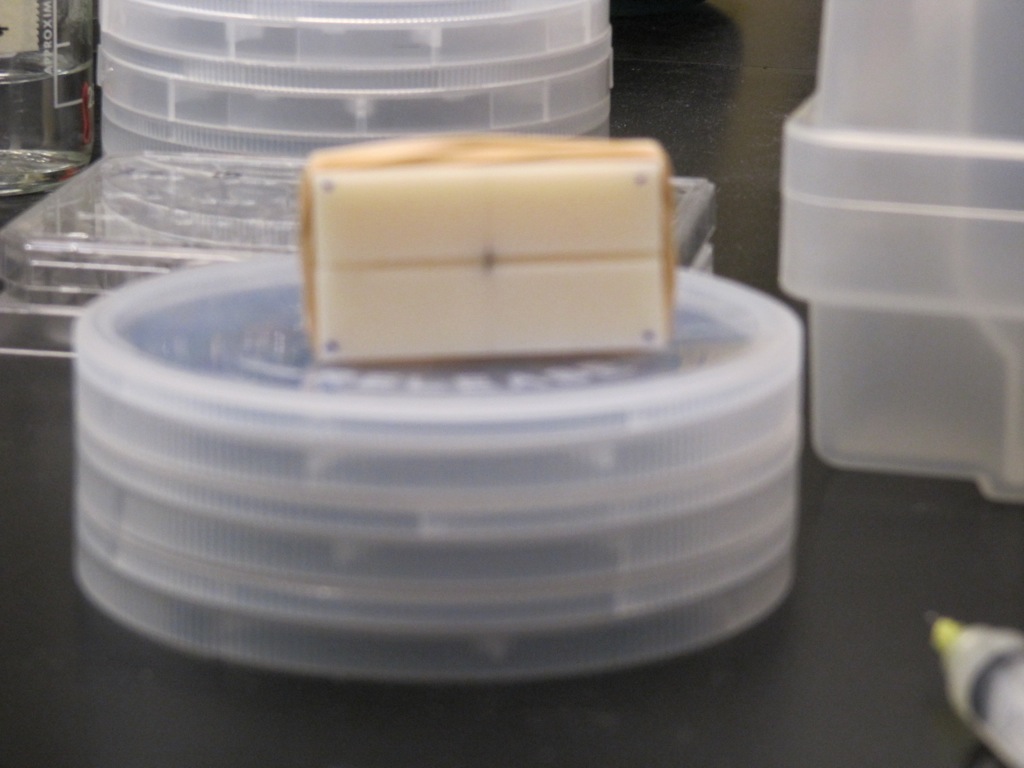
After reviewing these design issues, it was decided that a more reusable construct was required; one that would use a minimal amount of extra material and could easily track the pipettes to load onto both sides of the chip. A device was designed such that the track was machined onto two blocks. On the inside of one block there was a slot drilled to match the width of the circular TEM chip. Using this design, after two machined iterations, the device is now capable of aligning pipettes. Pictures of the device are attached to this post. However, how the chip is adhered onto the pipettes is still being investigated. One idea is to use ultraviolet glue to seal the outside of the pipette to the outer rim of the chip; however, this method will firmly glue the device to the Delrin block and thus cannot be used without careful application. It may be possible to affix the pipettes and allow fluid to flow without any adhesion all together. To accomplish this, a certain amount of force will have to be applied to the ends of the pipette. Nevertheless, without the force holding the pipettes to the chip, there is significant leakage between the four Delrin pieces.
Experiment 3:
The machining of the aforementioned device took approximately two weeks and in this time another method was developed to create an electro-osmotic device. This method utilized a horizontal pipette puller to force two pipettes together. The pipettes were then pulled apart and a chip was placed between them. While the device was suspended (pipette, chip, pipette), there was a copious amount of ultraviolet glue applied to the outside surface of the pipettes. The glue was placed in large enough amounts, covering the entire chip, to create a completely sealed device. However, some difficulties were encountered in the filling process. To ensure a complete circuit within the system, both sides of the chip had to be wetted because the surfaces are slightly hydrophobic and tend to resist an initial flow. However, pre-filling the pipettes is not an appropriate solution because they are under ultraviolet light during curing and the solution could evaporate during this process. Furthermore, the use of syringes or micropumps would rupture the membrane by their excessive force. The best wetting method to jump-start the device is to use the capillary filler (long slender syringe tip, approximately 5” long and is the color of copper) to form droplets onto the surface of the chip. Although there are no apparent short-term drawbacks to this protocol, this experiment does not appear to work for long-term applications. After two weeks, the membranes break and the mechanism is not understood. It is possible that the UV glue forms a matrix strong enough to shatter the membrane. It is also possible that the membranes ruptured through general use after two weeks. The membranes were not broken at the start of the experiment.
With these various experiments it became clear that there is more than one solution to this apparently simple problem. Although an adequate short term solution was found to test the electro-osmotic properties of the membrane, long term solutions must still be investigated.
Future Directions
1. Use a heat gun to loosen –OH bonds on the glass and silicon chips and bond them together. This process will eliminate the need for any adhesive material (i.e. glue). The gun is necessary to ensure localized heating. However, the lowest temperature setting on a heat gun is greater than that used on the crystallized membrane, so a voltage regulator will have to be placed between the outlet and the gun to modulate the amount of heat. The proper bonding temperature will have to be discovered empirically.
2. The Delrin mold currently comes in four pieces. The mold must definitely come in at least two pieces to ensure the 200 micron feature size for the chip slot. However, it may be possible to seal the gaps between all four sections using PDMS or crazy glue. Once this is complete, it is easy to exclude the capillary tubes and instead fill the tracks with salt solution.
3. From a manufacturing standpoint, it may be possible to design an automated device to glue the capillary pieces and chip together with a high speed and accuracy. Given enough time, an industrial machine could be designed that would hold the pipettes in place, apply a thin layer of glue on the normal surface of the pipette, and stick it to a suspended chip holder. If glue is not an appropriate solution, that step can be replaced with an automated spot heater to fuse the pieces together.
Additional Info:
Here is a user guide on experiment #3, using the best method found so far
Watch a broken membrane drip fluid.
Look at the design Layout