Reducing Fluoropolymer Buildup on MgF2 RIE Process
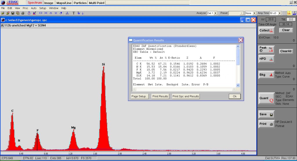
I have a preliminary result from Kevin that there is a layer of fluoropolymer remaining on my MgF2 freestanding nanomembranes (which could explain some of the carbon signal in EDX from my previous posts). This would create another unnecessary signal for the intended Raman spectroscopy application. Remembering an old graph from my schooling, I dropped the etch pressure and increased the amount of oxygen in my RIE process:
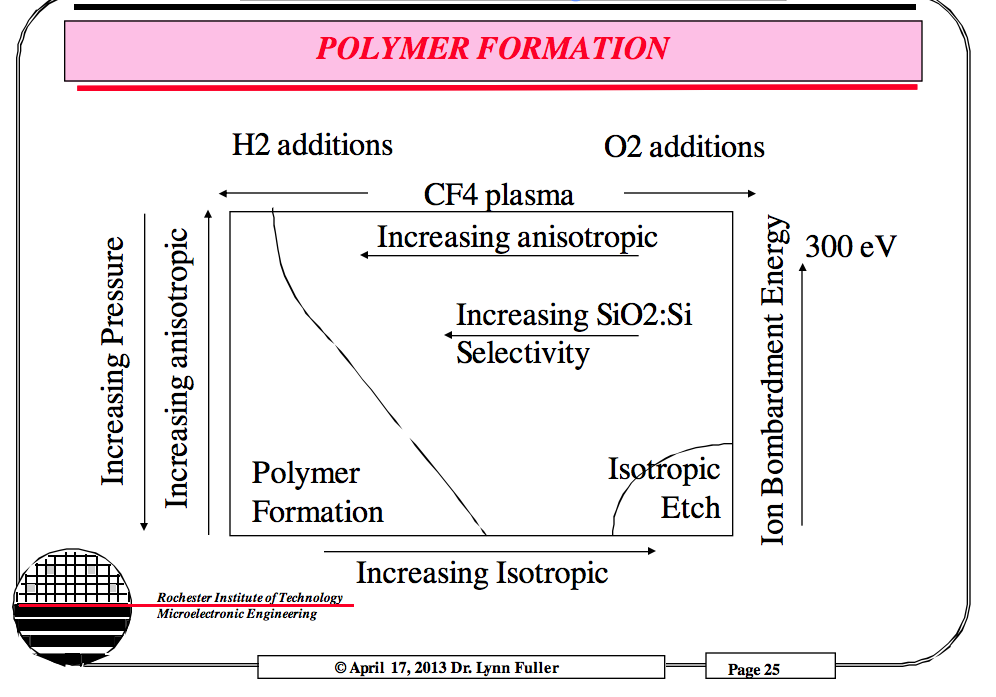
Old Recipe:
- 100-125 W total power
- 5e-5 Torr base pressure
- 200 mTorr starting pressure (275 mTorr during etch)
- 95:5:100 CHF3:O2:Ar
- 120 s
New Recipe:
- 100 W total Power
- 5e-5 Torr base pressure
- 100 mTorr starting Pressure (150 mTorr during etch)
- 45:5:50 CHF3:O2:Ar
- 120 s
- Additional 30s of O2 plasma (100 mTorr, 100 W) to consume any additional polymer
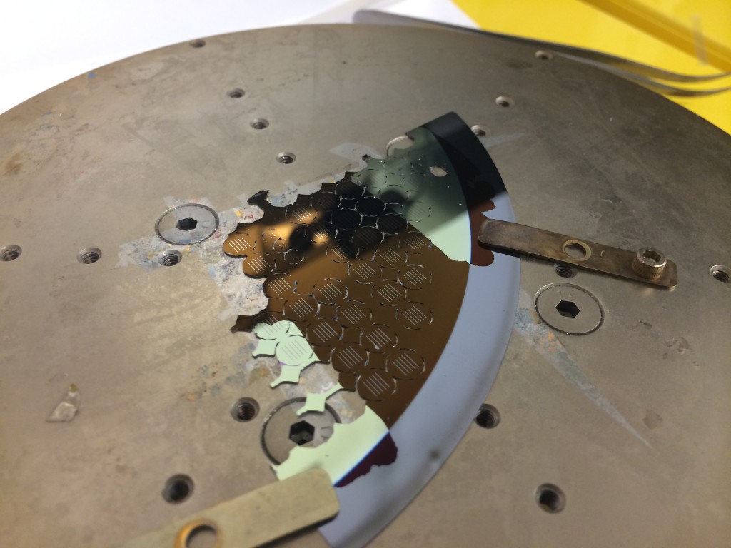
I evaporated ~50 nm of MgF2 onto a quarter circle of a wafer (1126, 50 nm NPN, 26 nm avg. pore diameter), using metal clips to hold the wafer to the platen. Then, I used the Right RIE tool in URnano to perform the backside etch release.
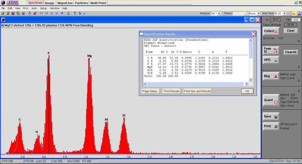
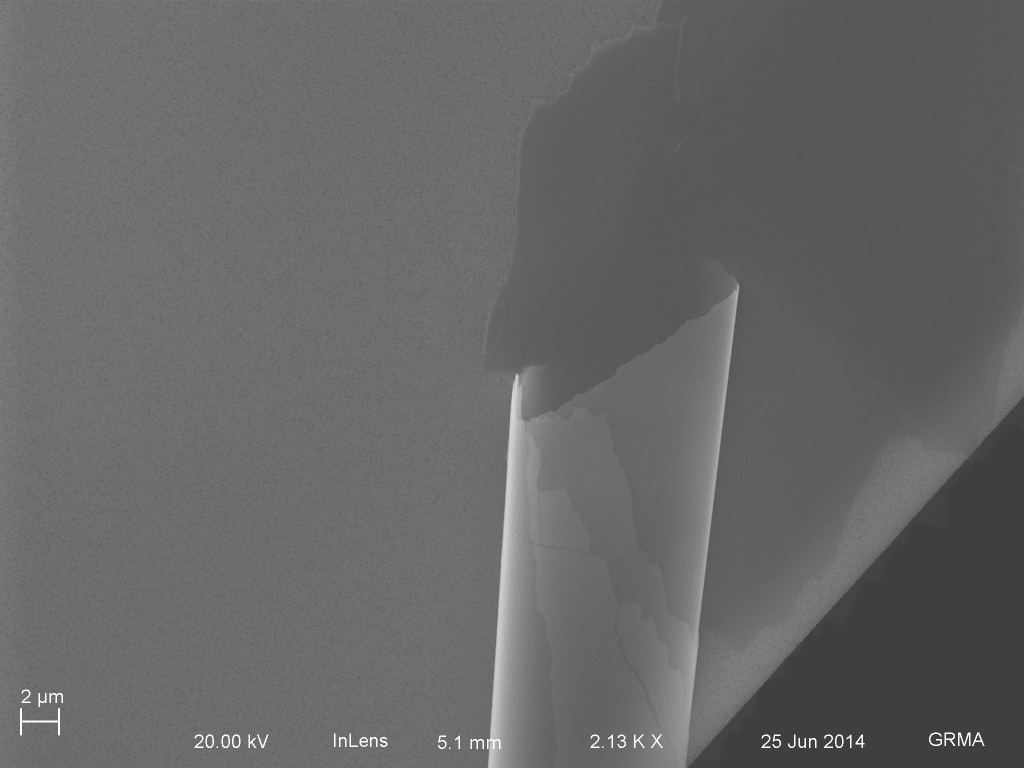
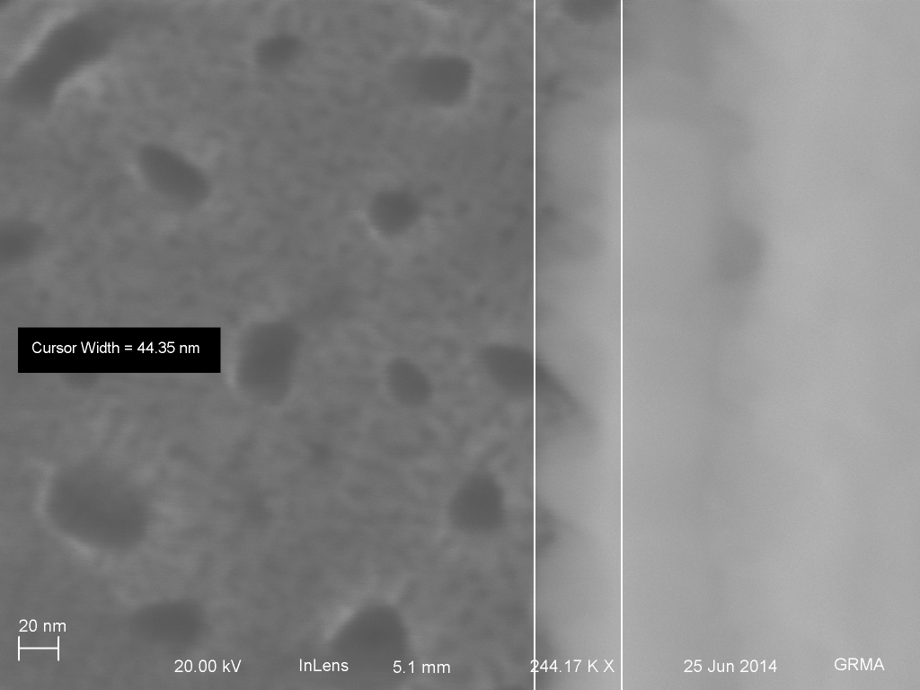
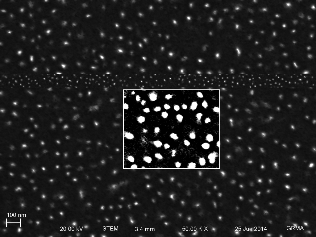

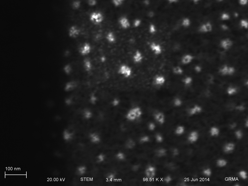
This process should remove most of the polymer formation, although I cannot easily verify it with my tools. However, the overall process yield dropped from 30-50% to ~15% (2 complete intact chips, 10 with some freestanding membranes, and 3 chips completely broken). One possible explanation for the decrease in yield is that some amount of polymer was contributing to the mechanical strength of the membranes, allowing them to exist in a tensile state. This does not bode well for the intended cell culture uses. Next week, I will detail my thermal annealing process for making the membranes stronger.