HUVEC Adherence on Microporous Membranes Under Flow
Introduction/Motivation
Endothelial cell adherence mechanisms are well characterized in literature to date. Endothelial cells, such as HUVECs, interact with their substrate as well as surrounding cells through focal adhesions (network of proteins involved in cell adhesion; vinculin, talin, FAK, etc.), VE-cadherins, tight junctions, and other membrane bound molecules. These molecules work in combination to allow cell signaling, molecular transport, and growth to occur. The ability of these cells to adhere to their substrate is key to healthy in vitro proliferation and function. Culture dishes typically made from tissue culture polystyrene (TCPS) are characterized by a hydrophilic surface that allows for basement membrane functionalization and healthy cell growth. The membranes created by SimPore, namely NPN and NPN-O, have been shown to provide a viable surface for static and dynamic HUVEC culture, however, dynamic cell culture on 3 um pore membranes results in major cell loss over the course of 24 hours (τ=10 dyn/cm^2), resulting in a non-confluent, poor representation of the intima. My experiments presented here, and to come, are focusing on the ability of HUVECs to adhere to microporous membranes under flow while attempting to elucidate a possible cutoff at which cells can no longer adhere to varying membrane porosities and pore sizes. Successful dynamic culture of HUVECs on microporous membranes will greatly benefit neutrophil and sepsis work in the near future.
Methods
Cell Culture
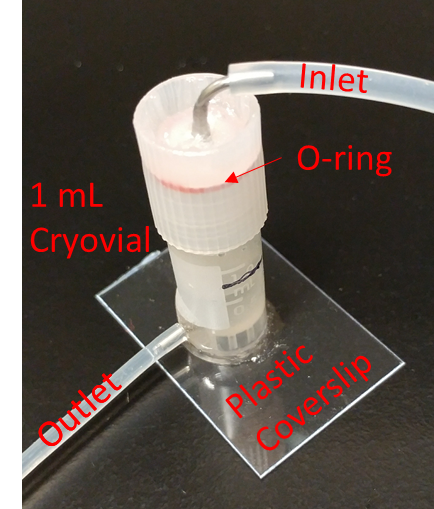
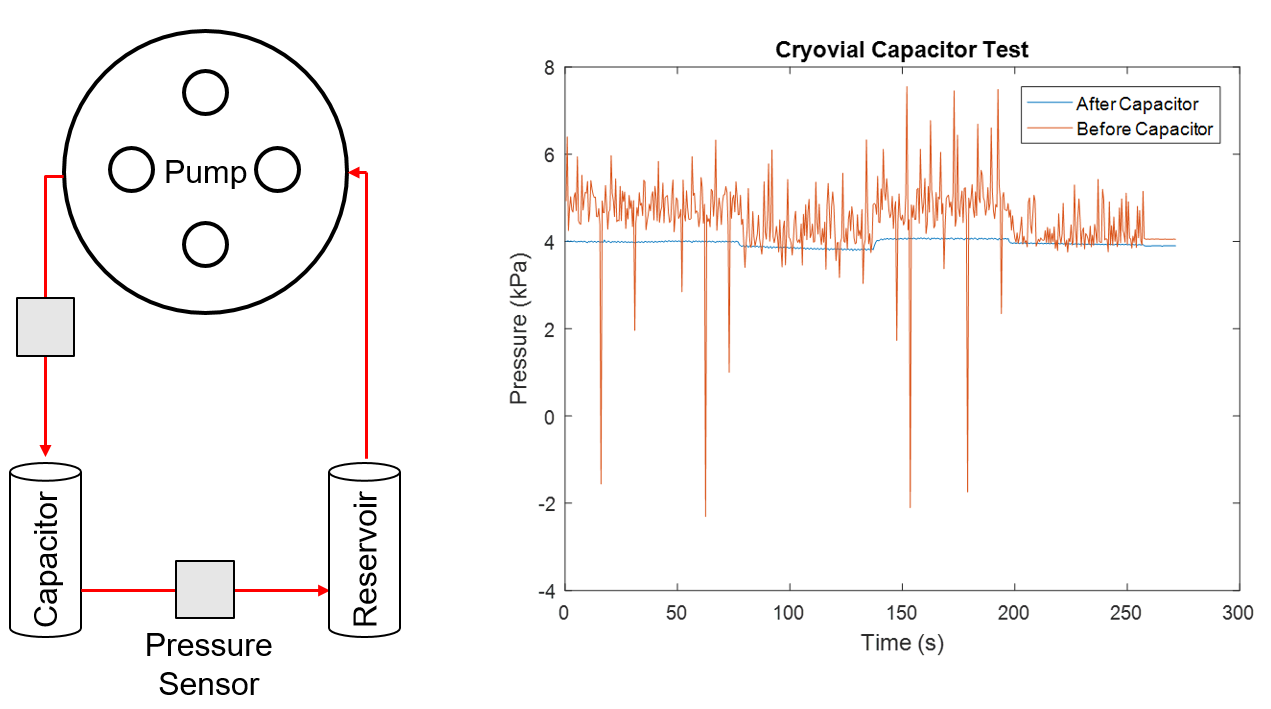
Microfluidic devices were designed with 130 um top and bottom channels (double sided tape) that allow for quick removal of gaskets for imaging. Wafer 4655 (0.5 um LP) chips were used for these experiments. The devices were exposed to UV light for 30 mins for sterilization prior to use. The top channel of the device was functionalized with 0.6 mg/ml human fibronectin for 1 hour at RT under the hood. The blood vessel-on-a-chip pump circuit was assembled without the device and allowed to run with MCDB 131 media for 15 mins in the incubator. Due to difficulty of cleaning after using the cuvette based capacitor, the capacitor was redesigned as seen in Figure 1. A pressure sensor test confirmed that the capacitor is sufficient in dampening the pressure jumps caused by the peristaltic pump (Figure 2), while a separate test confirmed that it provides a consistent flow rate of which we can base our shear stress calculations.
HUVEC perfusion was performed as usual: One confluent T-25 with HUVECs was suspended in 300 uL of fresh cell media and perfused into the respective devices in 100 uL volumes. Cells were left to grow to confluent for 24 to 48 hours prior to flow. Flow was applied to achieve an approximate shear stress level of 12 dyn/cm^2.
Results
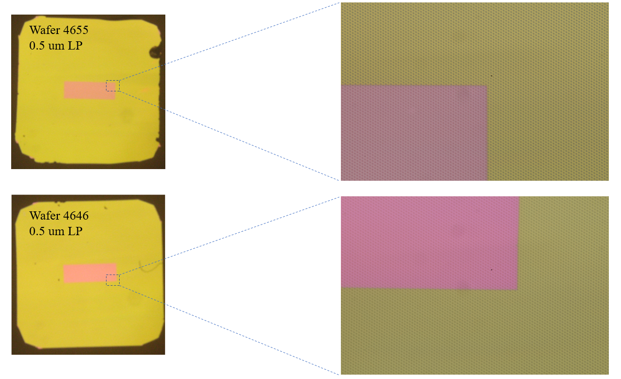
Following 24 hours of flow, HUVECs showed some degree of remodeling while remaining mostly adherent to the membrane surface. The LP chips have a pitch of 1:3, meaning the space between pores is equal to 3 times the diameter of the pores themselves. The chips we were provided for this experiment were labeled 0.5 um LP, however, they appear to be high porosity (1:1 Pitch; Figure 3). For this reason all calculations will be based on high porosity pore spacing.
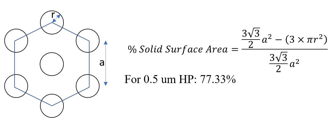
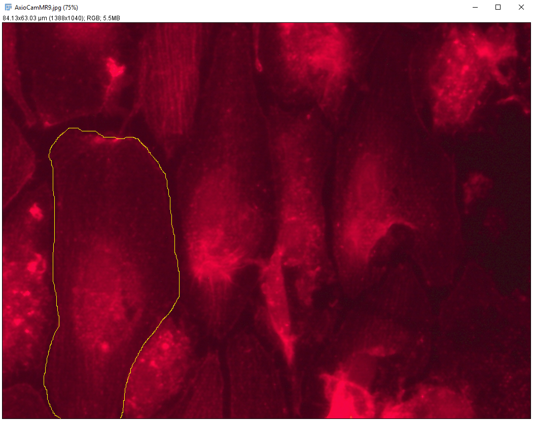
Using a formula derived based on hexagonal packing of pores, the area of the membrane that the cell can actually adhere was calculated (Figure 4). ImageJ was used to estimate cell area based on phalloidin stain (Figure 5). The average cell area was measured to be around 750 um^2. Together, this data suggests that an average cell has about 580 um^2 of surface area to adhere to. Using this number, we may be able to quantify a max number of focal adhesions able to form in a given area and correlate that to cell adherence under flow (going forward).
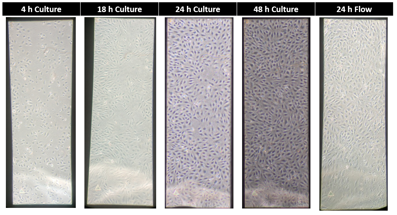
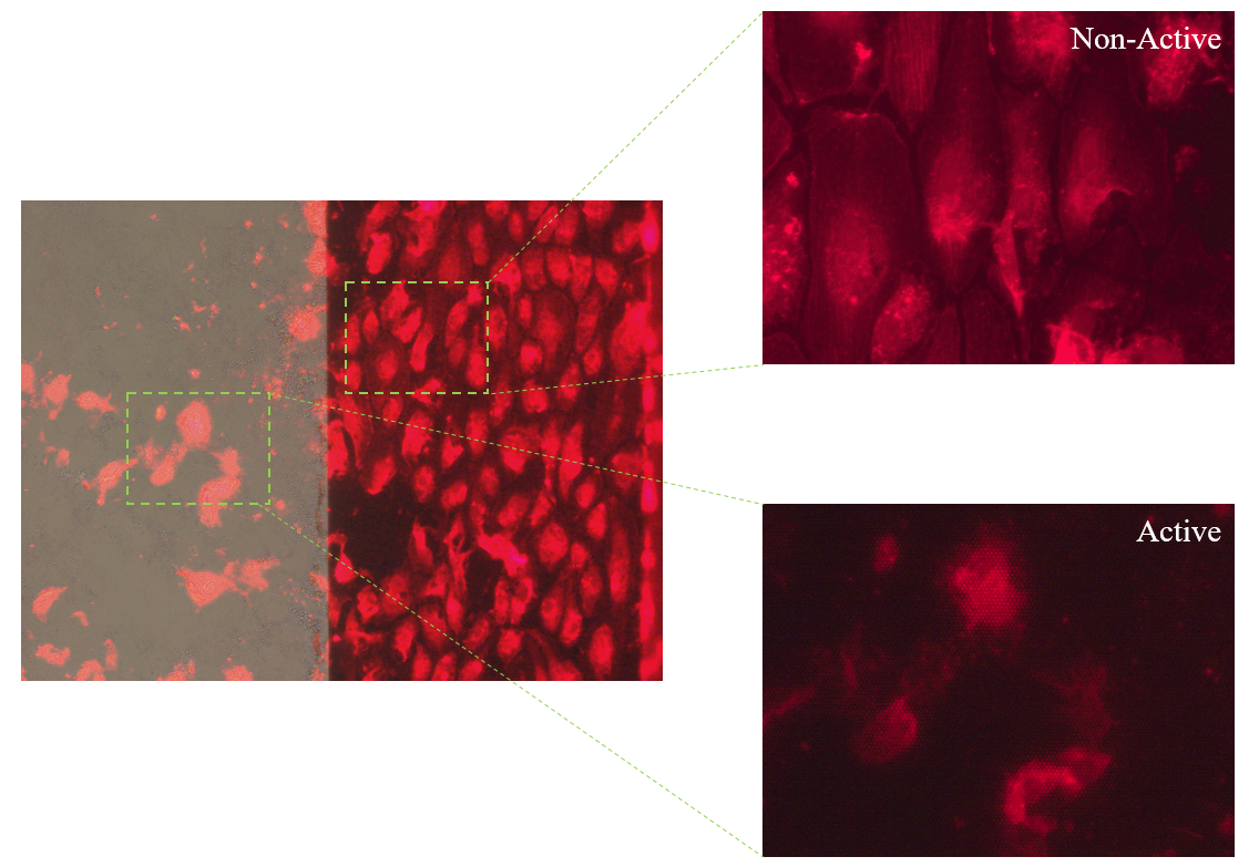
Under brightfield microscopy, adherence after 24 hours of 12 dyn/cm^2 flow looked promising (Figure 6), however, 48 h of flow was sufficient in shearing off all remaining cells (Not Shown). Phalloidin was used to image cells on the non-active area of the chip. As seen in Figure 7, cells immediately to the right of the active area of the microporous membrane look healthy and well aligned, where as the cells directly on the active area are few in number and rounded. This elucidates an interesting phenomena, as it suggests that cells are able to successfully adhere through the pores to the scaffolding material. This post is a start to a larger aim, involving varying shear levels, chips, and time points, that I plan to layout in the coming weeks. Any suggestions or feedback would be very helpful going forward.