Continuing my work from last week, Tucker used the same tenting (NPN, vapor transfer) and incubation procedure (20 nm and 60 nm Au particles) on an oxide substrate with posts (200 nm high). The substrate was dessicated in the 70C oven overnight. No additional platinum or gold coatings were made. The sample was tilted slightly on the SEM stub, so I used a tilt compensation of 10 degrees to keep everything in focus.
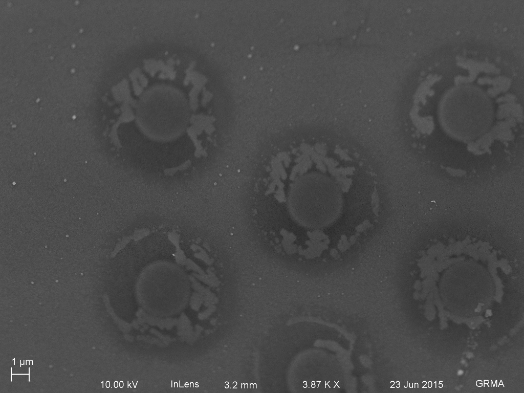
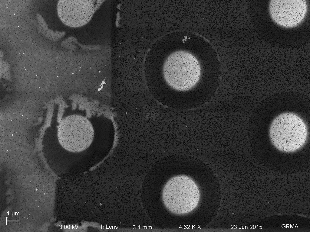
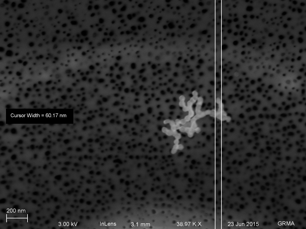
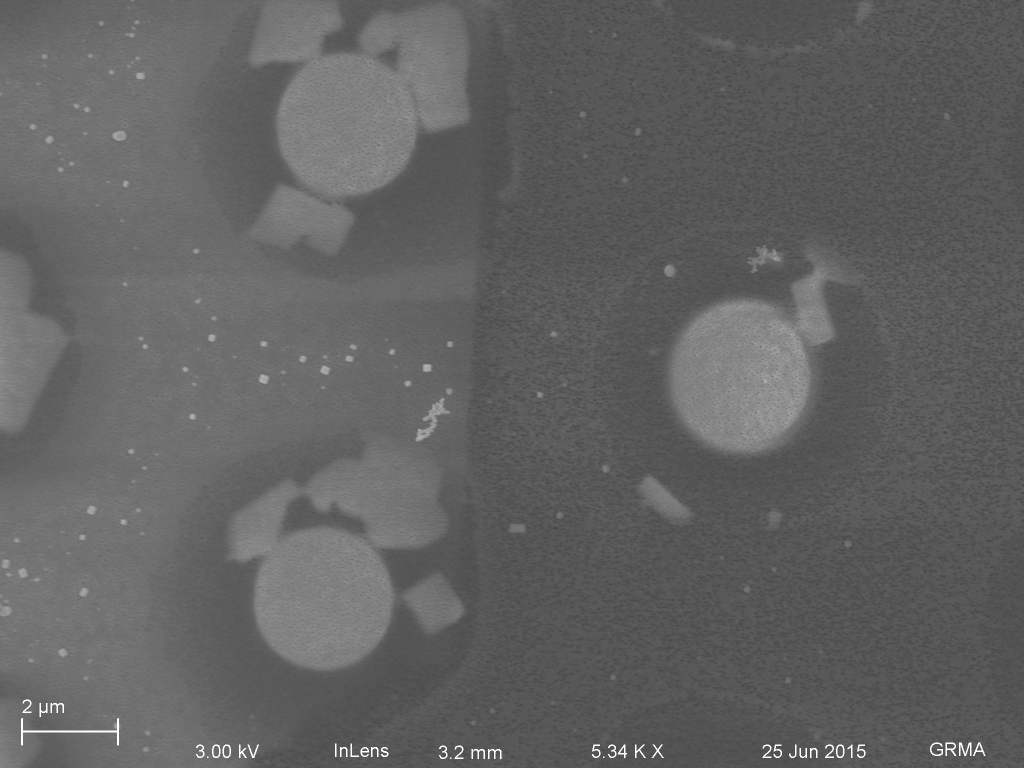
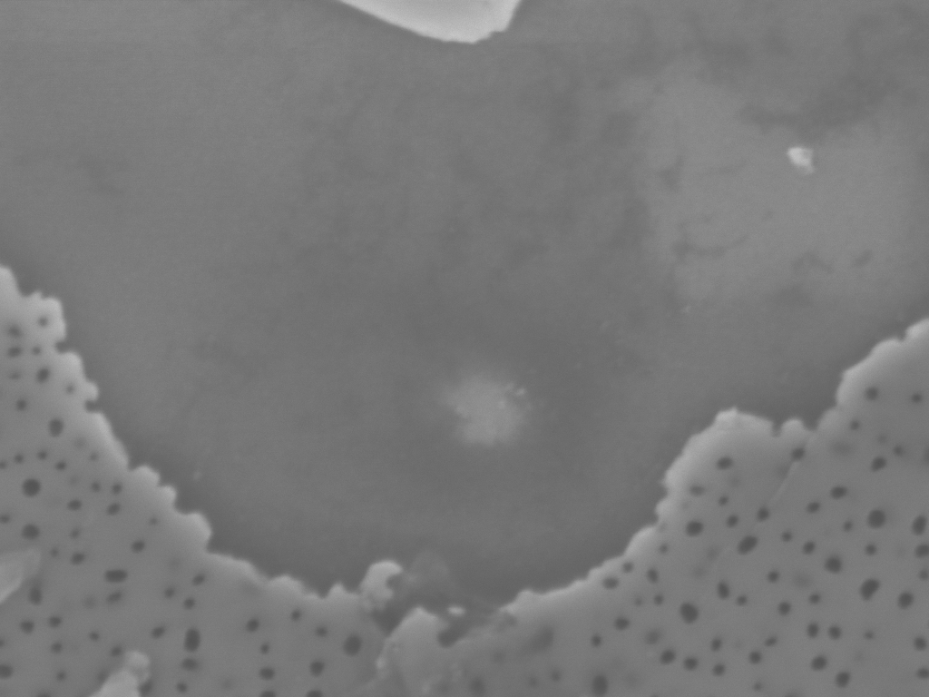
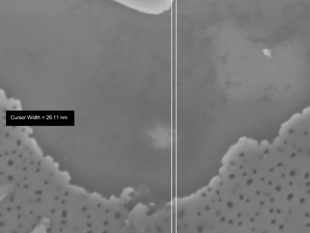
Image without tilt compensation. The items are blurry in the top portion of the image.Oxide patterned region with tented membrane over posts. The tented region consists of rings around each post. Some of the rings have an interesting high contrast pattern on them.Freestanding region tented pillars are on the right, and tented regions over the substrate are on the left. Some have high contrast, which is most likely a residue from drying or potentially particles stuck underneath. There are a few small salt crystals (cubes lower left) in the image.60 nm Au aggregates on top of a tented region.There are many holes, but no single 60 nm Au particle could fit through any of them.Small 25 nm particle near hole.Tented pillar region over substrate.
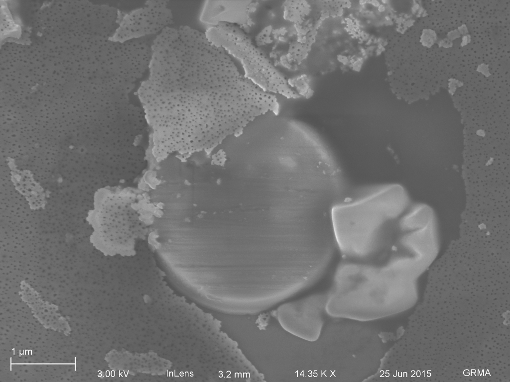
Magnified view of this pillar with large nanoparticles on top of the tent, and smaller ones occupying the holes.
Next, we will have to break the nanomembrane tent and see if we can observe particulate on the bottom surface.
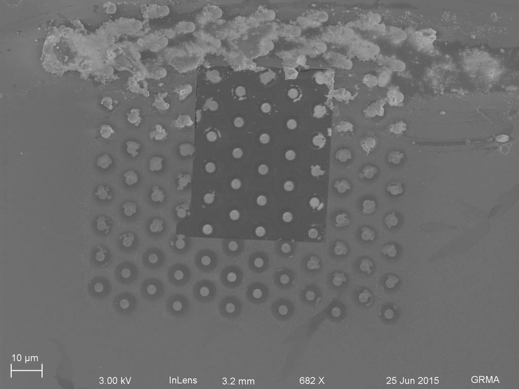
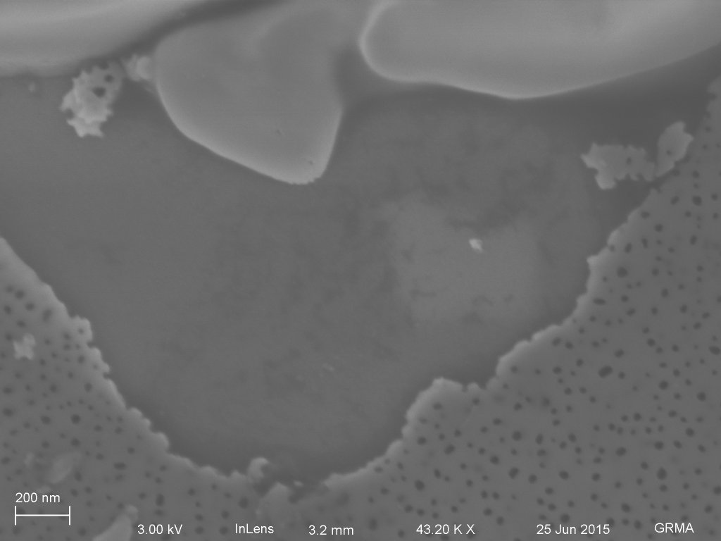
Update 6/25/15 – We broke the tent
No metallization yet, just scratched the tweezers across the surface.
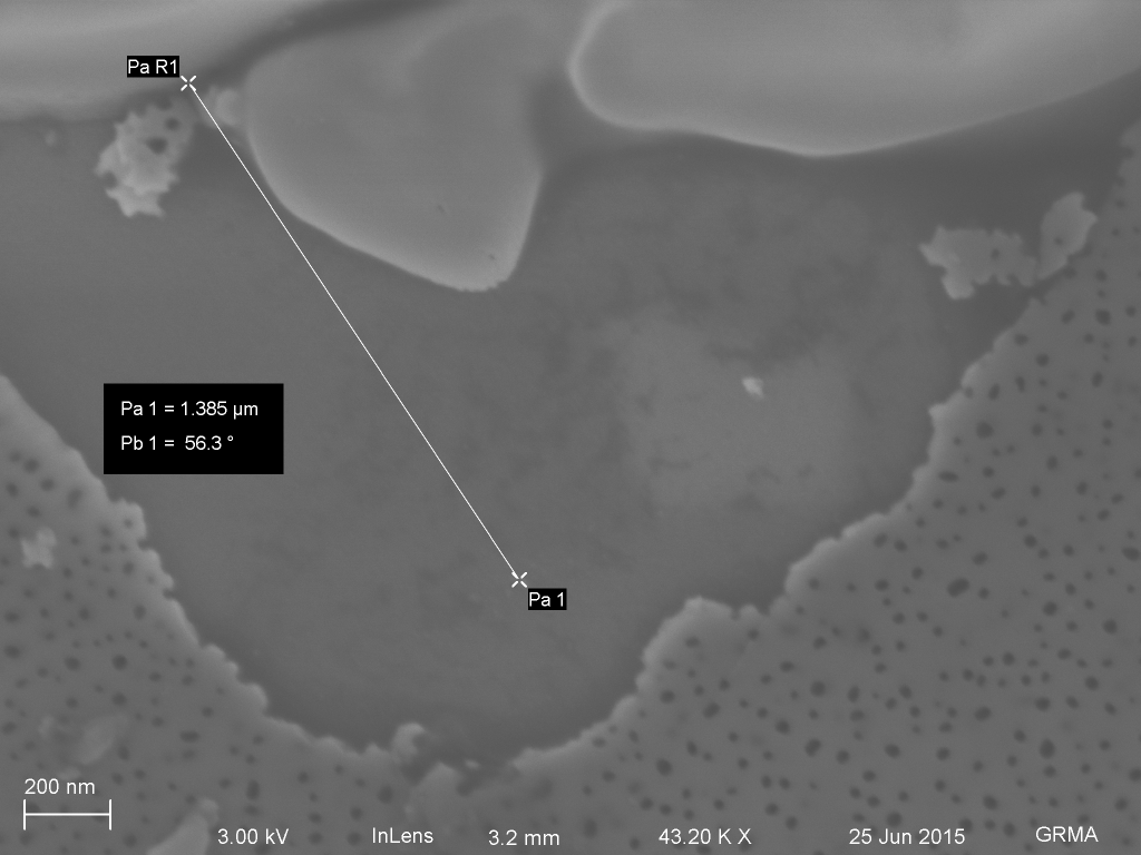
Large scale particulates (60 nm aggregate) are mostly in place)Broken post. The tented radius is about 1.5 microns.Broken area near post, which would have been under tent. Nanoparticles near bottom part of imageDistance to particles
Particles are about the right size.
I’m going to metallize with platinum to get clearer images.
Here is the figure we talked about in the last meeting. For each specific membrane, I’ve plotted both the experimental permeability and the permeability calculated from the theory. You can see in some cases they are close, but in others they can be pretty far off. Omitted from this chart are retests. Updated: Graph is…
The movable cutoff gels were more or less successful, but were too dirty for publication (see knowledge page). I’ve been trying to rerun them so that they look nicer, but the darker stain that I used has brought out a few new observations. The first gel following this paragraph is the new gel. The second…
Simpore produced a wafer of 50 nm NPN with a matrix of (4) widths X (5) lengths Widths of 100 um, 300 um, 500 um, and 700 um Lengths of 1 mm, 1.5 mm, 2 mm, 2.5 mm and 3 mm Each chip has one membrane. These are the dimensions of the membranes. Using the burst…
So this is basically an update of my post from a couple of weeks ago (and a figure from the poster that I just put up), but it is a very good status update of the contamination experiments that I have been running with XPS. Basically, I ran the sample that had been purified by…
Prior Post w/original data and images UPDATE: In the couple plots below, the minimum dimension has been changed to aspect ratio (minimum dimension/maximum dimension): For constant perimeter: alpha=1.1930, beta=.2005, gamma= -0.1380 And for constant area: alpha= -0.1624, beta= -0.0060, gamma=0.2922 In my last post I explained an experiment where multiple features were put on a single sample…
As I mentioned in my previous post, there are a lot of problems associated with the technique for testing the ability of a CytoVu assembly to act as an assay that I had been trying to use before. Several possible sources of error were apparent, such as the difficulty inherent in consistently pipetting such small…