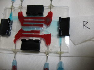
Blood and PBS in large Lift-off device.
I attempted to clear the large format lift-off devices (from Josh). I was unable to clear, in a reasonable amount of time (< 2 hours) by pumping IPA. So I switched to PBS then Blood and blue-dyed PBS (dye is estimated to be between 10 nm and 500 nm, obviously the amount of dye near 10 nm is slight compared to that dye too large to diffuse, I reach this conclusion not from this experiment but in experiments with clear PBS and dyed PBS for which I was unable to upload images). With the surface mostly unwetted the blood did a good job sticking to the membrane and gaskets (as evidenced during the post experiment autopsy). Sorry no photos of that, but the blood did like to fill in the SU-8 support squares.
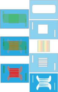
The first image is what I expect, I’ve used blue for the gaskets, and green for the PBS (dialysate) and red for blood. The membrane is striped in the illustration. I didn’t mix up the colors to be confusing, but I seem unable to let go of my preference of using blue for PDMS.
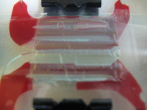
The next image shows the dialysate side of the device, as you can see not all the blood delivery channels are filled and the membrane is quite wrinkled.

Another image of the blood and dialysate in the device.
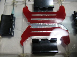
This image is from the blood side, showing the blood better filling the channels, though still not fully filled. The dialysate can be seen to be ‘selective’ in is flow path. This is undoubtedly due to the fact that the gaskets are not bonded in place and are in fact free to deflect vertically and come into intimate contact with the ‘ceiling’ or ‘floor’ of the flow chamber.
In this image, you can see both the ‘selective’ flow, as well as the blood in one of the diffusion channels in the PDMS subjacent to the blood delivery channels. I can’t easily tell from these images how much of the channels that are in contact with the membrane are filling with blood, as they should.
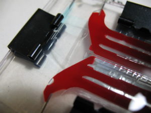
This final image really shows the preferential flow of the dialysate (blue dyed PBS).
After these experiments, I pried apart the device, the blood delivery fluidics gasket was well bonded to the glass slide and the membrane, of course, was stuck quite well to anything it had contacted, top or bottom. But is is unclear how well the inner blood channel walls were bonded to the blood delivery fluidic gasket. I’m not sure how well these gaskets were aligned but they do seem to be off in both along the flow direction and perpendicular to it. I would think the perpendicular alignment is critical for both optimized diffusion but for even flow into all of the diffusion channels (aka inner blood channels).
If we are going to use 2″ by 3 ” glass, or plastic, the I think we need to redesign the flow, optimizing it for the lower flow rates I use for animal experiments. I especially would like to get rid of the need to turn 90º. We can flow from one end of the slide to the other, I would also like to have one blood input and one blood output. We need to discuss the best way to have a stable fully bonded gasket system so we don’t occlude flow of either dialysate or blood. I would be willing to go with a gasket to allow a choice of one-to-one or two-to-two ports for the blood where a shared third port could be blocked if using the two port set up and the the two ports could be capped if using the single port. It’s clear in my head how this would work. This, of course, is one of the many things I’m supposed to be working on in my new research…
In a nut shell, I think we need to go to a serpentine channel for now. This should solve most of the aforementioned issues, albeit with some caveats (non-ideal length-to-flow rate etc..). The wrinkled membranes are something that we have not found a way to eliminate yet (happens when transferring), but hopefully we (Dean) can work around that for now.
“…but the blood did like to fill in the SU-8 support squares.”
These devices are assembled such that the SU8 is ‘up’ or on the dialysate side, so the quote above is confusing/concerning. Dean can you expand on this: How do you mean ‘fill in the SU8?’ Is it possible that the blood is just exposed to transmembrane pressure such that it collects only where the transient pressure (through the SU8 windows) can hold it there, thereby clogging the active area of the membrane?
Josh, good catch on the SU-8. It was during disassembly, yes I pried the device apart after the experiment and the blood left in the channels was allowed to flow onto the dialysate side of the membrane. Sorry for the confusion. Since I was unable to clear the bubbles and blood met the gaskets and membrane dry, I wouldn’t expect to learn much about what the blood is doing. One of the problems with the needle approach is the unswept area if the needle is inserted too far into the flow channel, you can see large bubbles at three of the ports (only one outport has no large bubble). I can withdraw the needles such that the lumen is at the edge of the flow channels but I had prophylactically hot-glued these in before the issue came up.
As far as redesign, Tucker i redrawing with the next round of rat studies in mind, with a target for urea clearance of kT/V = 1.2. The current design was optimised for different flow rates. If this next redesign doesn’t resolve or at least greatly ameliorate the filling problem then serpentines could certainly be considered.
The wrinkling membrane won’t be an issue as the chambers/channels are high enough to accommodate the flexing. There are some areas where there is only the depth of the ‘diffusion channels’ without the added depth of the delivery channels. (diffusion channels are superjacent to the membrane, the delivery channels are those with the ports)
Tucker’s redesign is well and good for the continuation of the project past June, but first and foremost we need to get the bench top tests we promised in the grant. The best way to achieve this is to change over to the serpentine and stick with the smaller devices. The larger membranes work ok, but consume too much of the wafer to make it practical with our short deadlines. Right now we are looking at about a 20% success rate on the LO process, so the large membranes we can get about 1-2 avg. whereas we can get 3-5 of the smaller devices per wafer.