SEM FIB Lift-out of 50 nm NPN for TEM Analysis
As a step to identifying the particles that I am capturing in my systems, I am attempting to do an immunogold labeling with a CD 63 primary antibody and a 10 nm gold conjugated secondary. It is possible to run this analysis in an SEM, but the best confirmation method is using a TEM and correlating the presence of the gold nanoparticles with lipid vesicles stained with uranyl acetate. If both of these are present, then we can say for certain that we are capturing exosomes on the membrane. Therefore, this analysis is extremely important. The thickness of the NPN membranes is perfect for TEM analysis, but the size of the chip makes it impossible to just put this sample into the TEM. This means that we need to find a method to be able to take the membrane and put into the TEM.
In the UR Nano facility, Brian McIntyre has been working on a technique using the FIB to generate small cross sections for TEM analysis. The process involves cutting the sample with the FIB and then taking a small piece (on the order of microns) and cutting it out and then welding it to a TEM grid. They have been working on this technique for small samples and I thought that we might be able to apply it to our system. If we could cut a chunk out of the membrane and weld it to a TEM grid, then we can perform the analysis that we want while running the experiment with the right type of chip. This would be the ideal situation, but there is a drawback in terms of the time required to do this process.
Time requirement aside, on Wednesday, I sat down with Ralph (one of the guys who works with Brian) and we started the process of lift-out. I had previously labeled my sample with the immunogold stain using a modified procedure from JOVE (http://www.jove.com/video/3037/isolation-and-characterization-of-rna-containing-exosomes, doing steps 6-10 for the exosome labeling for imaging by electron microscopy procedure with a pre-fix of 30 minutes with 2.5% glutaraldehyde and then a wash in 5 drops of DI water after the uranyl acetate step. Each droplet was 50 uL instead of 30 uL.) and I critically point dried the sample immediately afterwards to hopefully improve membrane integrity.
After 4 hours of work, (and much nail biting) we were able to remove a 100 um x 100 um x 150 um triangle from the membrane and weld it to a TEM grid. This was remarkable for several reasons: The first is that this is the largest sample that they have ever lifted out and welded, the second is that the membrane did not curl (as you can see later in the images) and a third is that even after removing such a large chunk of the membrane, the overall integrity of the membrane remained. That means that I still have this chip sitting on the sample mount, with what appears to be an intact membrane, which you can tilt to the appropriate angle and see a small chunk missing.
This experiment has provided us with a technique to take our NPN membranes that are in the 5.4 x 5.4 mm chip format and remove a part for TEM analysis, which is something we were not previously able to do. It has also led to the revelation that these membranes are super strong and can survive a portion being completely removed, which has implications for further burst pressure experiments. (Jim would like to create defects in the membrane and then analyze the burst pressure and the breaking point.) With this taking 4 hours (even though it was the first time that we had done this, so we can probably reduce that) SEM FIB lift-out is perhaps not the best technique for high throughput of samples, but it is very high precision and can hopefully lead to some very revealing data! Keep your eye out in the next couple of days for a post with the results of the TEM analysis, because either way, those will be very interesting!
And now for the images!
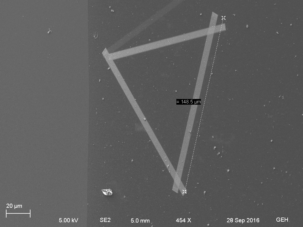
Figure 1: Platinum deposition outlining the area to be cut with the FIB.
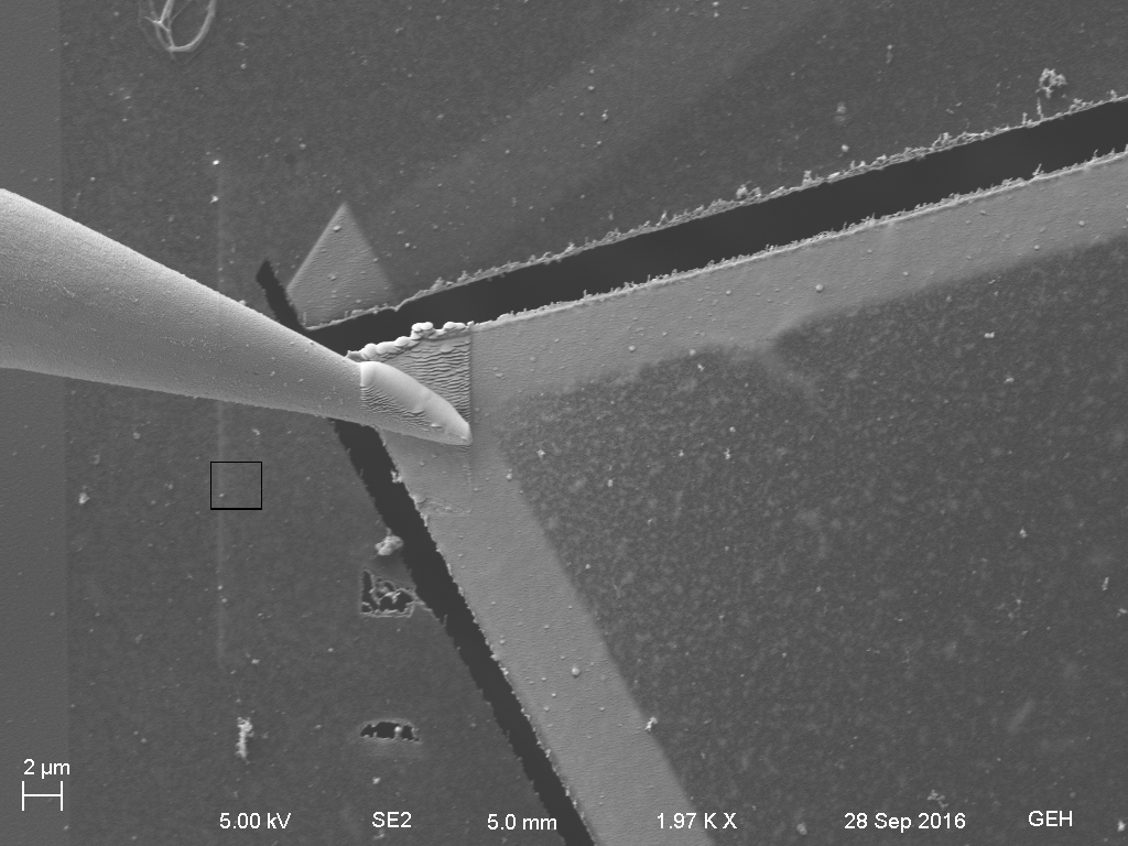
Figure 2: Image of the tungsten probe welded to the membrane piece with platinum.
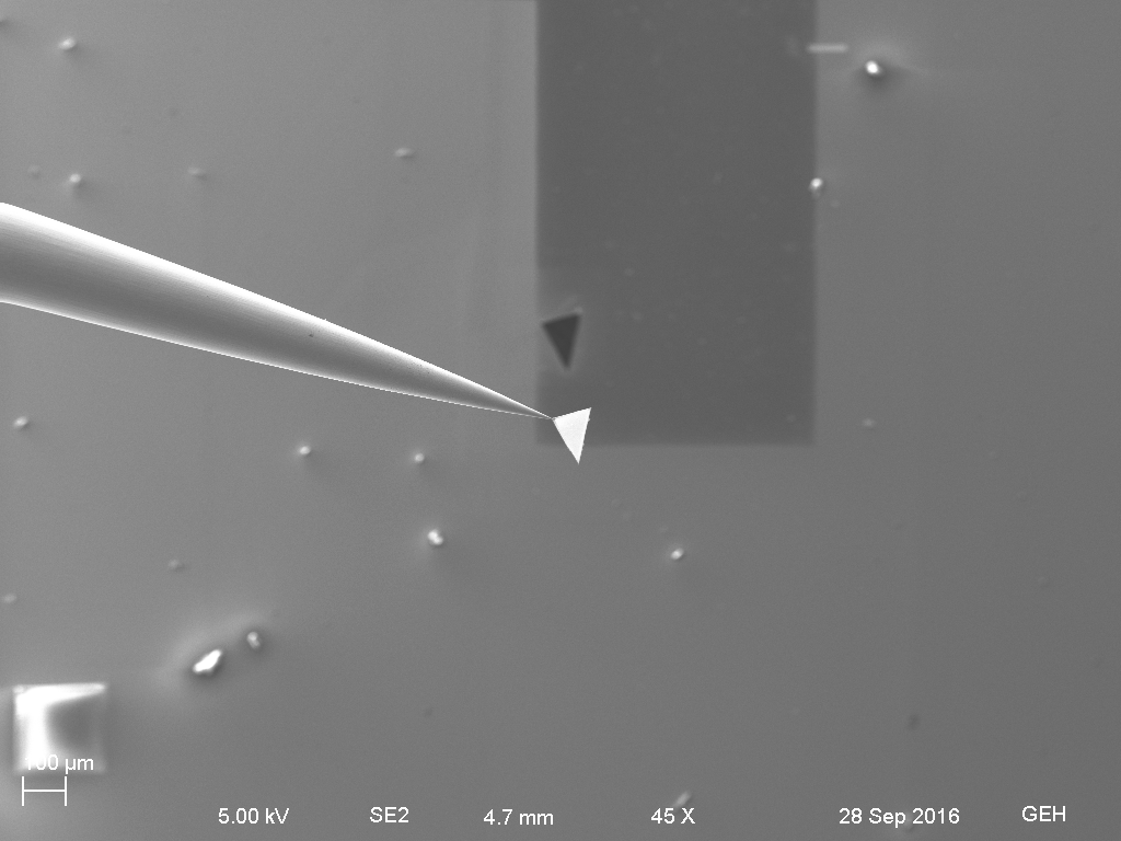
Figure 3: The membrane chunk welded to the probe fully removed from the membrane.

Figure 4: The intact membrane minus the lifted out portion. Note how remarkable it is that it is still fully intact.
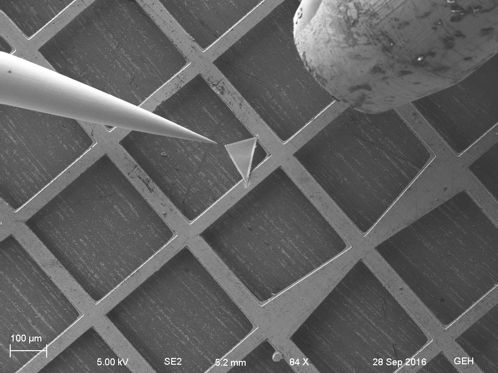
Figure 5: The membrane welded to the TEM grid with the probe cut off and the platinum injector (right).
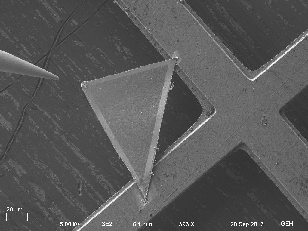
Figure 6: Close up of the welded membrane piece. Note a small amount of folding in the membrane, but for the most part it is flat on the grid. The weld is a two point attachment.

Figure 7: Close up of a FIB test cut of the membrane.

Figure 8: The original membrane surface post lift-out. There is no gold coating on this sample, so the very small particles are most likely gold nanoparticles associated with the antibody labeling.
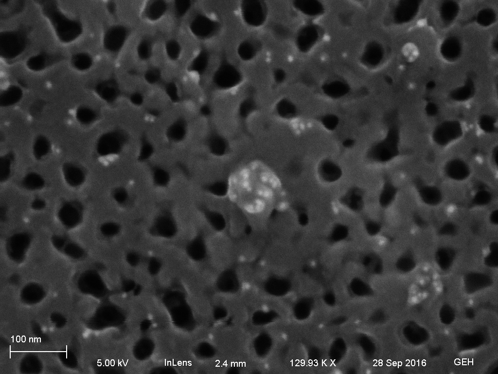
Figure 9: Close up of a particle on the membrane surface showing a cluster of the gold nanoparticles. This is most likely indication of antibody labeling of the particle, but this will be hopefully confirmed in the TEM.