Ensuring cell adhesion on microporous substrates under shear flow
Just to give a brief background, I have been working with endothelial cells to make a microvessel mimetic device, and one of the important requirements for endothelial cell culture is to be able to grow the cells under physiological levels of shear stress. Further, since I am trying to achieve neutrophil transmigration through the endothelial layer in the subjacent ECM, I have to use a 3 micron porous membrane for the flow-based culture. One of the important challenges I faced was to retain the cells on the membrane and not let them get washed away. Pore area for a 3 micron pore is pi*2.25 = 7 sq. microns. Even if I am using a low porosity (5 %) microporous substrates, the regular absence of 7 um square surface area seems to be detrimental as far as cell adhesion is considered. In the past, I tried nanoporous membrane, high porosity silicon nitride membrane, and more recently low porosity microporous glass material. Nanoporous membrane works great; cells adhere nicely and can sustain the shear stress and don’t get detached. Silicon nitride on the other hand, and microporous glass as well, do not offer the same results though! Check my previous post on the same issue.
I thought that if I put a collagen gel on the backside of the membrane that will resolve my ‘back-flow’ issue caused due to membrane deflection [check the link for my earlier post for detailed description of this back – flow business]. Once the gel gets polymerized in the trenches, it will prevent the basal media from forming the jet streams through the porous holes, and will stop pushing me cells. Unfortunately that didn’t help; cells still detached. It also proved that positive transmembrane pressure wasn’t the root cause behind cell detachment, but the inherent lack of adhesion was (seemingly)! The following montage proves this observation when I plugged the basal side of the microporous glass membrane with collagen gel.

We even saw the ‘decapitation’ of the cell body- the cell used to get attached to the gel underneath the substrate and the remaining cell body or the ‘torso’ used to get washed away. I tried collagen 1, geltrex, 4 % APTES but in vain. That’s why I concluded that it’s not the coating or anything else, but the inability of the cells to form continuous bonds with the substrate, which is causing their detachment.
But this gave me an idea: what if I am growing the cells on the gel instead of the membrane. So I inverted the chip, and seeded 3mg/ml of collagen gel in it and decided to use this inverted configuration for the shear experiments.
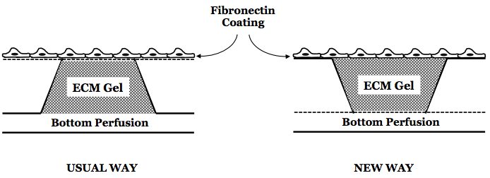
I also found a paper, which tried to do a similar thing. They seeded similar collagen gel on the top of a transwell, and then coated the top of the gel with fibronectin for cell adhesion. The RGD binding site is often inaccessible in collagen gel (that’s why people must be using gelatin, which is denatured collagen), so it’s better to treat the gel surface with fibronectin. I hoped this will work, but …

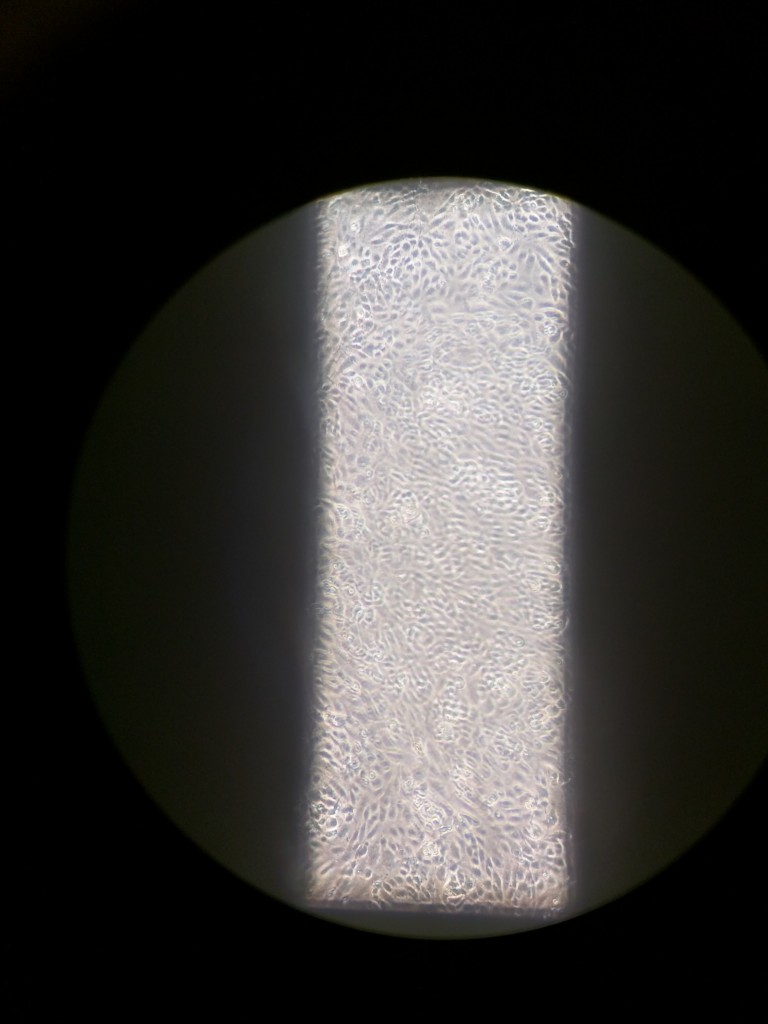
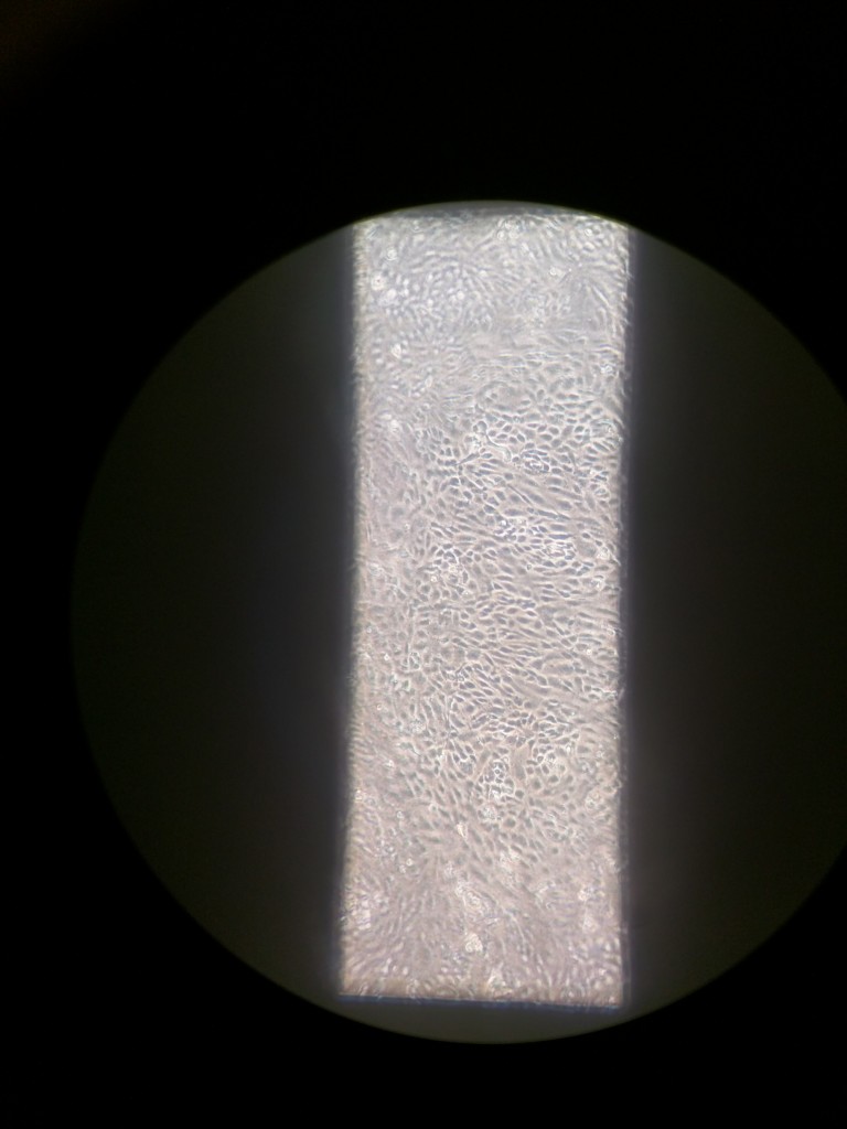
Notice the image on the top left. All the cells are in focus, but the edge of the membrane is not. That’s because they are grown on a gel suspended inside the trench, and the top surface of the gel is at least 600 micron above the membrane (300 micron is the gasket layer holding the gel, and 300 micron trench which also hosts the gel). As soon as I start the flow, something happens! The gel is compliant even at 3 mg/ml, which is on the higher side of the spectrum as compared to the physiological values. Since the gel lacks any stiffness as such, as soon as the flow starts, the gel bows down, and so do the cells on the surface. In the image in the top right, notice how the cells in the cell are out of focussed as compared to the radially external cells. The image on the bottom left focuses on these cells that bowed inwards due to flow. Also notice that these cells [bottom] are more closer to the membrane surface (almost in focus with the edge of the window), as compared to the cells on the periphery [top right image] (different focal plane from the edge of the window). This is bad because the 600 micron gel simply bowed down along with the cells. This not only causes imaging difficulties, but also affects cell alignment. The flow is still laminar, and the cells still do get aligned in the direction of the flow. However, since the flow changes its direction a lot, while flowing through this pit, the alignment is all over the place, and cells are multi-directionally aligned. Look at this low-mag image to understand this.
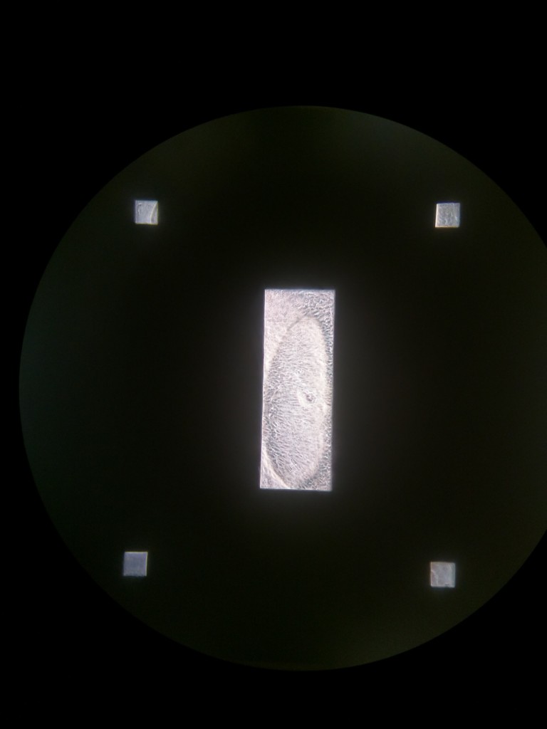
The oval in the center shows the ‘bowing’ down of the gel in presence of shear stress. I though increasing the thickness of the gel might render some more stiffness to the gel, and will reduce its compliance. However making it thicker didn’t help me at all. The same results repeated. Then I thought, what if instead of making gel taller and thicker and thus increasing its ‘bowing’ amplitude, I make it thinner. Thinner gel means reduced bowing down effects, and lesser out of focus cell-imaging. So I decided to use a thin 100 micron gasket on the top of the window. I reverted back to the original configuration of the chip, i.e. the flat side facing up with cells on the top, and the trench side facing down. I seeded a thin layer of gel in the square pocket created by the 100 um gasket; I added 5 ul on the top and sucked away the excess liquid to render a thin and flat layer of collagen gel on the top. Also I used the 3 um low porosity microporous glass membrane. Seems like this configuration works!

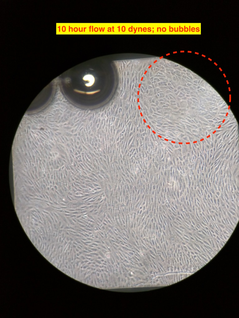
The cells were seeded on the gel and allowed to grow under static condition for about 24 hours. After that I started the flow at ~3 dynes/cm2 for 2 ish hours. I did so to ‘prime’ the cells to shear stress. This step is arbitrary and am not exactly sure if it’s at all necessary. Anyways, after 2 hours of lower shear stress, I bumped the flow rate to produce ~10 dynes/cm2 of shear stress. I am not showing the intermediate pictures; after 10 hours at 10 dynes/cm2 of flow, the alignment is visible. The flow is from the bottom to the top in the images. The flow is laminar just not mono-directional, due to which the alignment is different direction , but overall in the direction of the flow. There were few bubbles beneath the membrane, which are seen in the images. The image on the right has a red circle in the corner; there was a big air bubble at the egressing port of the channel, which got stuck and grew over time at that corner in the top channel. I was able to get rid of the bubble (although temporarily, since it reappeared over there eventually), but it didn’t leave without leaving dead cells over there.
Eventually there were many bubbles after 24 hours of flow. Troubleshooting them needed me to manually push them out using needles and syringes. That caused the gel layer to get delaminated at the front end, which faces the maximum impact of the flow.

I know the reason for the trapping of bubbles at the exit port; I need to redesign some of the gaskets to prevent them from getting trapped over the window. Overall this experiment was a huge success since this is the first time I was able to get aligned growth of cell under 10 dynes/cm2 of shear stress over 24 hour. More experiments to go!