Partial Etch RIE Blows out NPN Pores
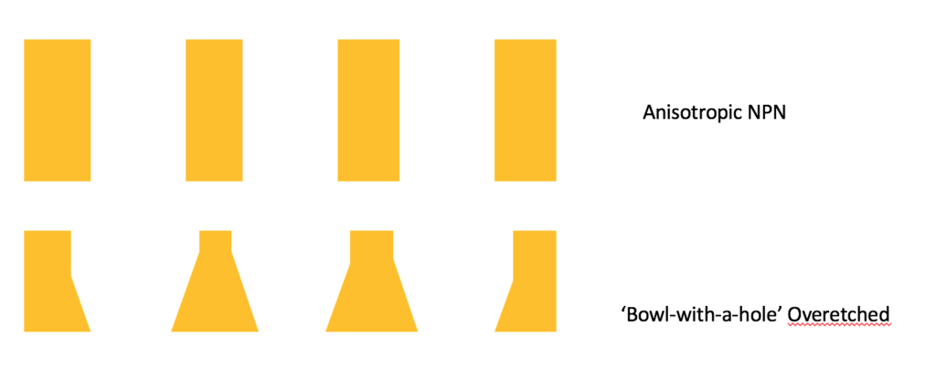
As the title states, this post is about shifting an arbitrary pore distribution in an NPN layer. Why would we want to do this? We believe that the underlying pore distribution and shape influences the properties of many of our devices (my SERS sensor work included). Jim has coined the term ‘bowl-with-a-hole’ to describe the difference between anisotropic features and roughened pores. The difference in structure results from a change in etch properties as the NPN is fabricated; the NPN etch is inhibited at the bottom layer by the formation of water vapor near the silicon substrate it rests upon. Over etching the membrane by a certain amount allows us to reach a final anisotropic NPN.
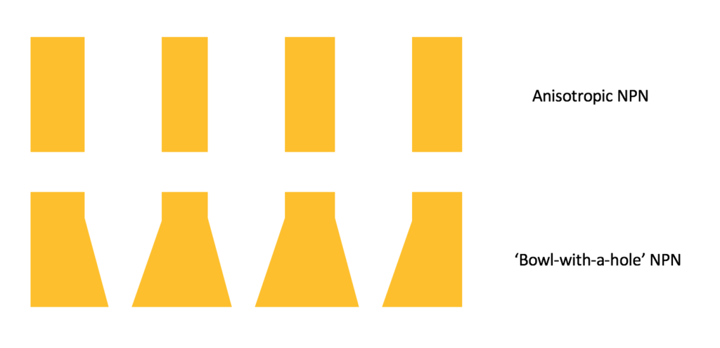
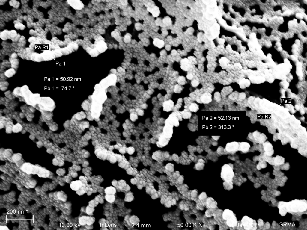
However, if we start with Anisotropic NPN and use it as a template, we can blow out the pores by using similar RIE processes (adding more oxygen to the mix), and broaden the pore distribution. This gives us a knob to turn to influence the properties of our membranes/devices, at the cost of thinner and weaker membranes.
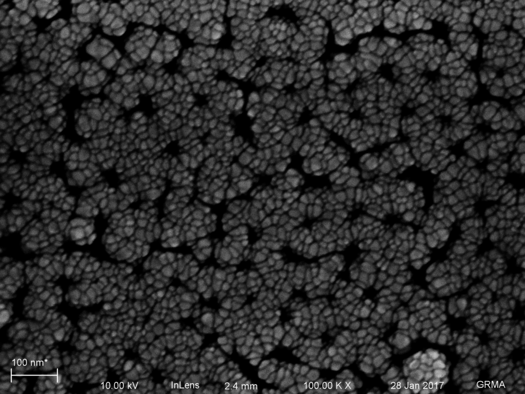
So I took 5 chips from wafer 1236 (9x 50um square windows, 50 nm thick NPN) and partially etched them in URnano’s oxford RIE with my NPN etching recipe, face up, in 10 second increments. After that, I imaged them with the SEM, which becomes harder as the membrane becomes thinner. Then I used the Denton Sputterer in the SEM prep room to add 50nm of gold to the membranes, and imaged them again.
Etching Settings
- 2.5 mTorr Oxygen (8.9 Setpoint)
- 47.5 mTorr CHF3 (26.9 Setpoint)
- 110/10 W Fwd/Ref
- ~100 mTorr Etching Pressure
- 5.5e-5 torr base pressure
- Samples face up on platen
- 10, 20, 30, 40s, 50s etching time
- In retrospect, I should have done a 0s etch with just the gas in the chamber too.
- I’ve previously clocked this etch rate at ~1 nm/sec
The chamber was first cleaned with a 5 min, 200 W, 100 mTorr Argon plasma, then seasoned with the etch recipe for 5 minutes.
Gold deposition setttings
- Denton Sputterer
- 100 mTorr base pressure
- Flooded with Argon 3x to purge chamber
- Samples placed face up
- no rotation
- 15 mA current
- 1 A/sec = deposition of 500s
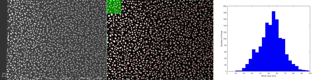
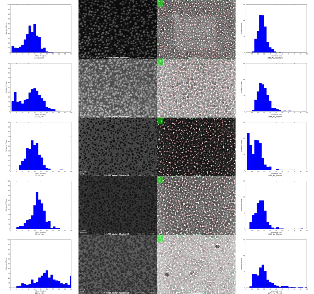
I used the pore processing software to form my histograms from 50KX images, following the pore processing manual. Some of the images were more difficult than others, because I had to rely on inverting the images to make the pores ‘bright’. The gold membranes in particular have many facets and crevasses, so I attempted to match that in the pore processing imagery.
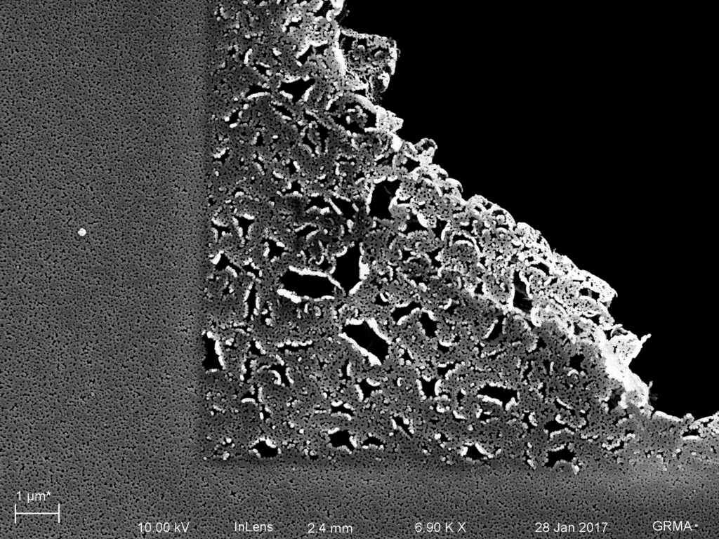
Seeing as all of these images are aerial images, we can get also get some crossections of these materials to see if the internal geometry has changed. Additionally, if we wanted to shrink the pore distribution, we could do so with ALD, or add material via evaporation (infilling).