Final Update over TE membrane
Hello Everyone,
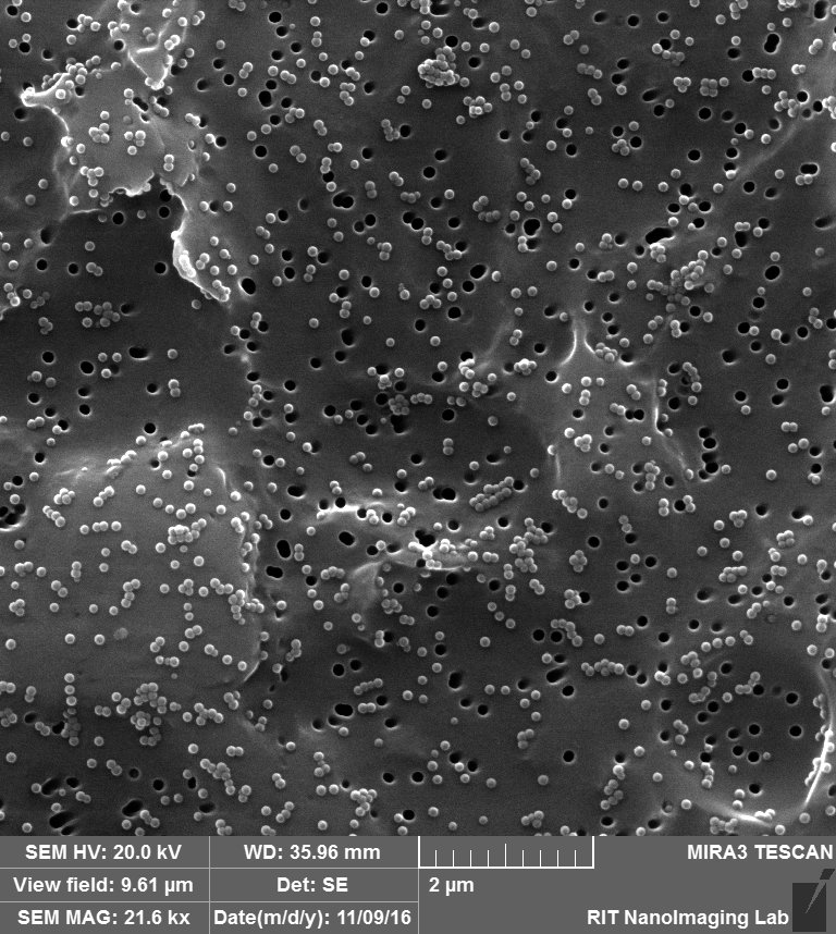
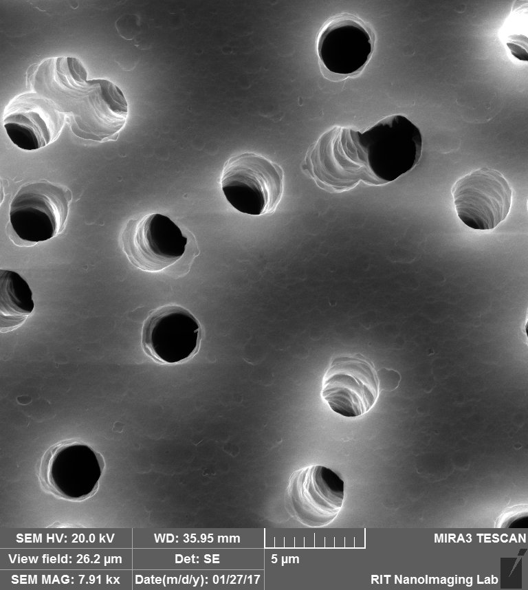
So first of all, a quick reminder of what i have been working on: we were able to show the trapping of the beads by TE membranes, although in final step and after releasing of the beads, we could still see beads on the membrane, so we hypothesized that the beads are attached to the surface of the membrane somehow. So we decided to do SEM over the membranes. So as you probably remember from my last post (link) , we could see that some of the beads are trapped on the pores, some are clogged in the pores and a lot of beads are just sitting on the membrane probably due to charge interaction or even during drying step, although the system was washed by DI water, there were still residual beads in the channel.
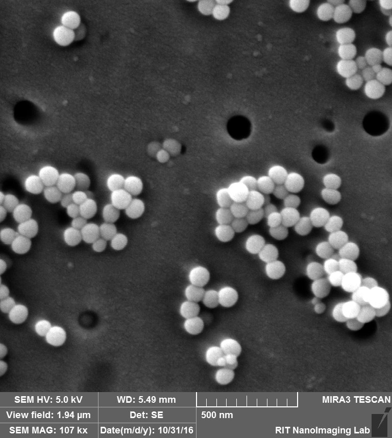


We thought that by covering the membrane surface with Albumin, we are able to neutralize the surface charge so there is no attraction between the membrane and the beads. After i did SEM over the membrane covered by Albumin, as you can see in the following images, we hypothesized that these features on the membrane are Albumin deposited on it.
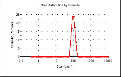
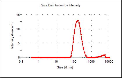
So the other idea that Jim told us was instead of coating the membrane with Albumin, coat the beads with Albumin. So as you probably noticed from the first images, beads that are just sitting on the membrane are aggregated and attached to each other, that could happen during the drying step or the beads were already aggregated before the process, so i checked the size of the beads with DLS before and after coating with Albumin. So the size of the beads would shift to larger ones after coating as you can see in the DLS for Beads in Google drive Link:
Before coating in BSA After coating in BSA
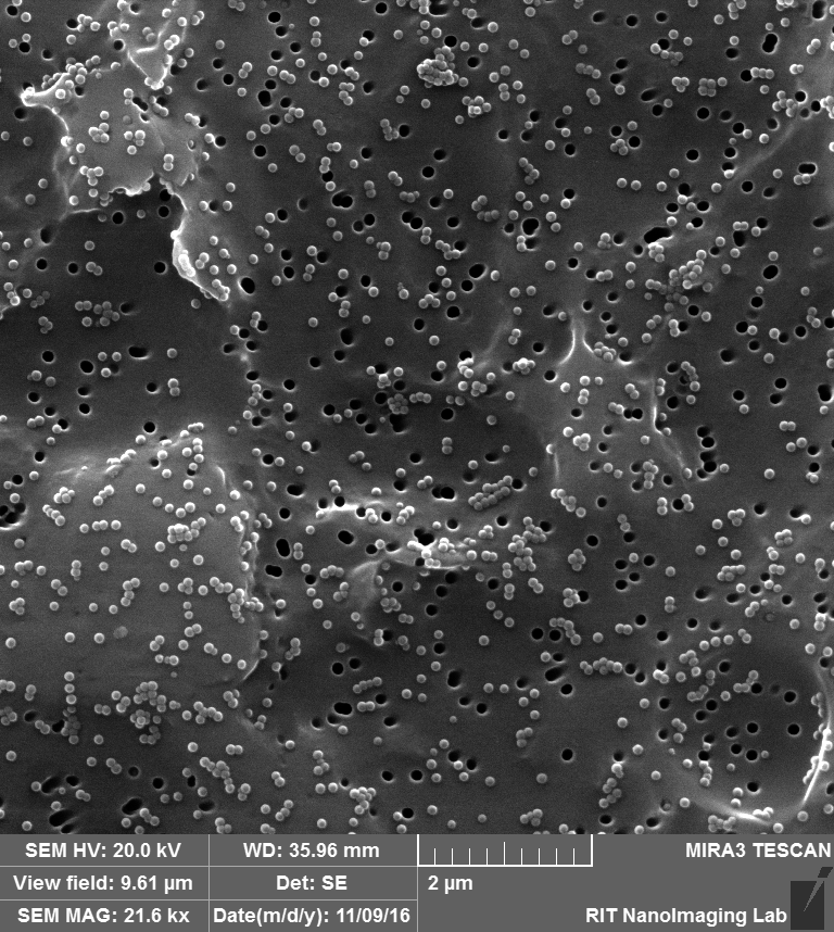
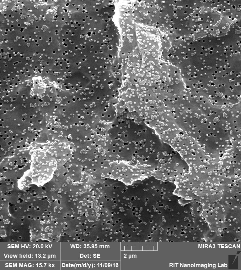
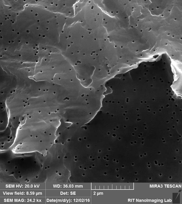
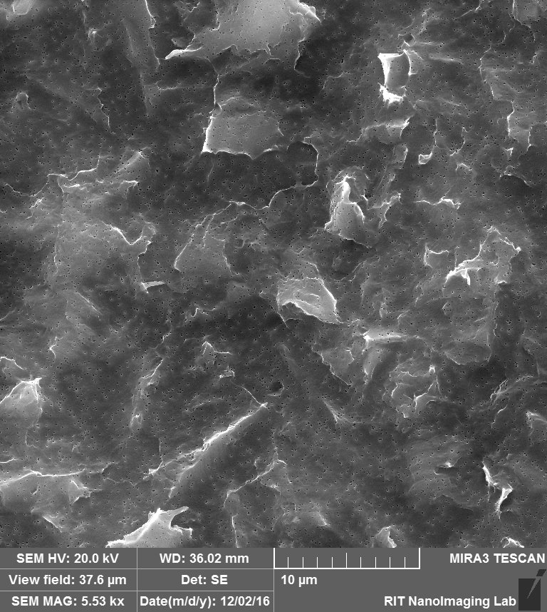
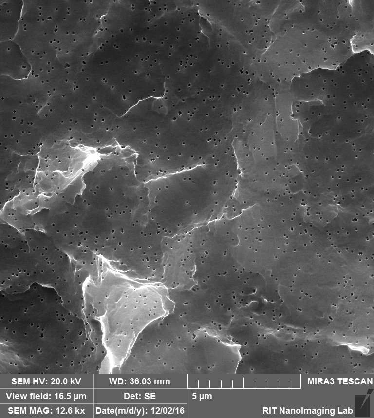
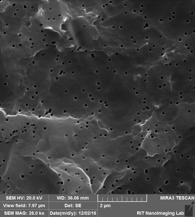
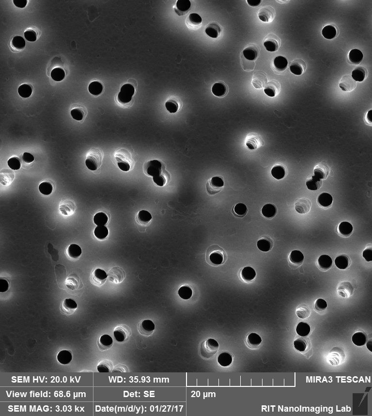
So for this experiment, i decided to image the membrane itself as the negative control experiment. By coincidence, the membrane was flipped, and i saw the same features that we assumed to be Albumin on the surface of the membrane, so by imaging the both sides of the membrane, we found out that one side is smooth and the other side is rough and textured, as you can see in the following images:
Smooth side:

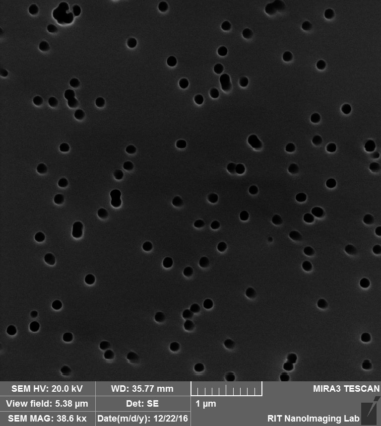
Rough side:
So then we realized that the company coat the membrane with PVP to make it hydrophilic, so we assumed that maybe the side with features was due to PVP to make it hydrophilic and the other side is uncoated and hydrophobic.
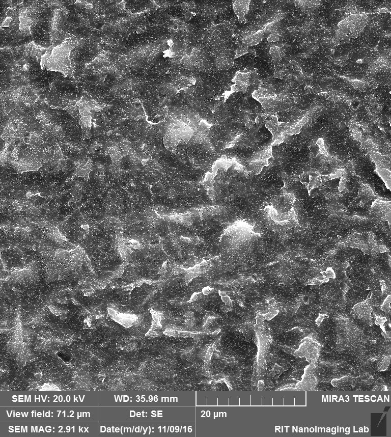
Then, i started to search to find a way to make the hydrophobic side hydrophilic by treating the membrane by Corona plasma device to increase the surface energy, and make it hydrophilic. So i did some simple wetting experiments that showed, treating the membrane by ozone would increase the hydrophilicity and wetting properties, but from the day that i started to treat the membranes, i saw more beads attaching to the surface of the membrane, so we assumed that treating the surface with ozone would increase the surface energy but also increase the surface charge, which leads to nonspecific absorption of the beads. Furthermore, in one of my experiments i saw a big hole on the membrane surface on SEM, it seems that the sparks would damage the membrane.
Then, i started to search for another method to have both sides with the same properties. I decided to call the company and they told me surprisingly, both sides of the membrane are hydrophilic and coated with PVP and those features are from the manufacturing process. They exactly told me that: “ This is just the difference in textures. This is from the manufacturing process of cast membranes. One side is smooth and the other is rough. “
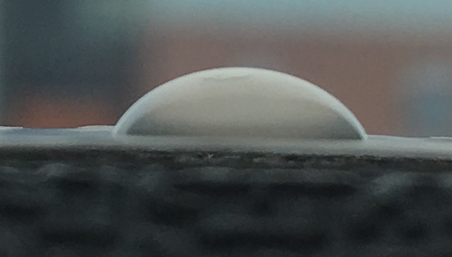
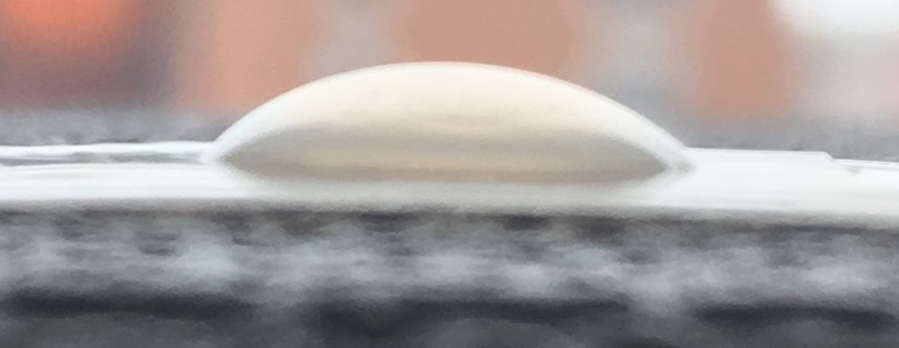
So then i decided to do contact angle experiments to see which side is more hydrophilic and to check if the company claim was accurate that both sides are functionally the same. We were assuming that the rough side with features is more hydrophilic. So as you can see from the following images that the rough side is slightly more hydrophobic than the smooth side, which was against our initial assumption.
Rough Side Smooth Side
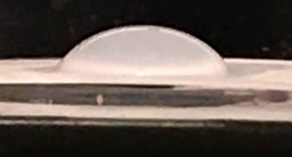
We also tried to wash away the PVP with rinsing by DI water to see what would be the differences, it is hard to tell any differences with previous experiment, but again the side with features on it is still more hydrophobic than the smooth and flat side.
Rough Side Smooth Side

Also i checked the membranes for our YAP experiments which are 3 micron pore size to see if those have the same features on them and none of the sides has the features as you can see:
One side:

The other side:

Finally, we searched to find some SEM images on the hydrophobic membranes to see if the same features are available on the hydrophobic membranes, so we found the linked paper http://onlinelibrary.wiley.com/doi/10.1002/ppap.201400044/full about plasma treating of hydrophobic membranes to make them hydrophilic, and they have the following figure of the both different sides of the membrane and this is what they said in the paper:

Untreated PC-TE generally has smooth outer surfaces with regular, cylindrical pores. SEM images from untreated PC-TE show that Side A is slightly more pitted with a clear grain/directionality, Figure a, compared to the expected morphology exhibited by Side B, Figure b. We suspect this sidedness starts at some point during the fabrication process and results in some variation between lots. Indeed, the rough morphology of Side A corresponds to a dull appearance compared to Side B, a distinction noted by the manufacturer. The pitting on Side A overlaps with many of the pore openings, an issue further exacerbated by plasma processing, making it difficult to identify the regular cylindrical pores needed for the pore measurement technique used here. Side B, however, exhibits the smooth surface and regular cylindrical pores expected with PC-TE and noted in our previous study of these materials. Pore measurements made using the series of SEM images from Side B show the weighted mean radius of as-received membranes is 117 ± 1 nm. This result is consistent with pore measurements made on the lot reported in our previous study and with the manufacturer’s specification. Given the well-defined pores on Side B, we restricted the rest of our PC-TE morphology and etch rate investigations to Side B.