Quick Characterization of 3D Printed Reverse Sepcons
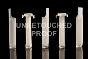
Photo Courtesy J. Adam Fenster, U of R
We’ve had several of each of the two prototype reverse Sepcon designs professionally 3D printed for us (top photo). I did a few quick tests to see how they worked in the lab.
“Fixed” Version

This is designed to snap onto the outer lip of a 2 mL Sepcon vial, and as a result does not slowly sink into the vial like the floating version (see final video in this post). Unfortunately, when the device is assembled with a chip and a bottom cover, it doesn’t fit all the way into the vial and cannot snap on to the lip.
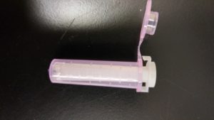
“Floating” Version
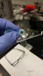
Once assembled, this version still fit nicely in the 2 mL vial, with a very slight resistance on the last 1 cm or so of insertion. The chip I assembled it with was from wafer 1070:

It’s a pretty standard NPN chip, with 20% porosity and average pore diameter 40 nm.
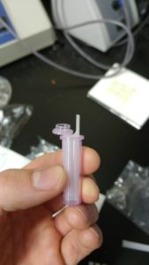
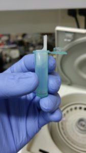
I found that when fully inserted, the area around the floating basket could contain about 350 uL of fluid before spilling over:
Further, filling the outer vial with 1 mL and then adding the floating basket did NOT cause the outer vial to overflow, which we had predicted after much math and discussion:
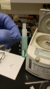
I put the above assembly in the centrifuge:
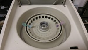
and spun at 1000 rpm for 1 min. After 1 min, nothing had gone through at all:
That’s actually good news – it means there are no leaks in the system, and 1000 rpm in that system is a pretty paltry applied pressure. So next I spun it at 3000 rpm for one minute:
And the chip broke, equilibrating the system. After both the 1000 rpm and 3000 rpm spins I checked the centrifuge for water, and found none (there also appeared to be the same volume before and after by visual inspection), meaning nothing escaped over the lip of the outer bucket.
Finally, now that I had a broken chip, I made a little video of the vial slowly equilibrating:
The vial stops moving 1 cm from the end due to the bit of resistance I discussed at the beginning of the post, and I was impatient so I forced it down and caused a droplet to escape. But that’s not what usually happens.
Conclusions:
“Fixed” vials need a design change to be useful at all.
“Floating” vials appear to have no leaks, do not force fluid out of the top of the outer basket under normal operating conditions, and work well in the centrifuge. They can process 1 mL of fluid easily, with an expected ratio of filtrate to retentate of about 2:1 (target was 10:1, or 100 uL remaining in outer basket after processing 1 mL, but we have about 300 uL remaining at the end of a separation).
EDIT: Another spin was done with the chips. It took about 20 min at 3000 rpm to reach equilibrium with the same 1070 chips. By pipetting out fluid in measured quantities (a not particularly accurate method) I found 620 uL of fluid in the inner vial, and 250 uL in the outer vial, which is a slightly better ratio.
So both systems need redesign? Or is there possibly a centrifuge tube that offers less resistance for the moving design? Is it not possible to spin through this resistance with the current design to achieve something better than 2:1? Even 4:1 might avoid a redesign.
And did you wet the inside before trying to get flow through?