Variability of Shear Induced Endothelial Cell Alignment on Various Substrates in a Microfluidic Device
-Intro
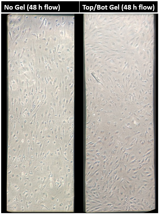
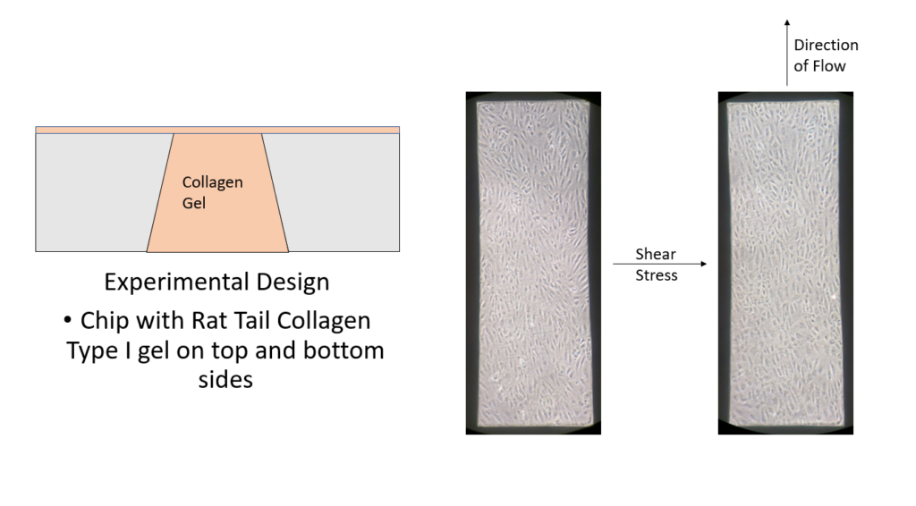
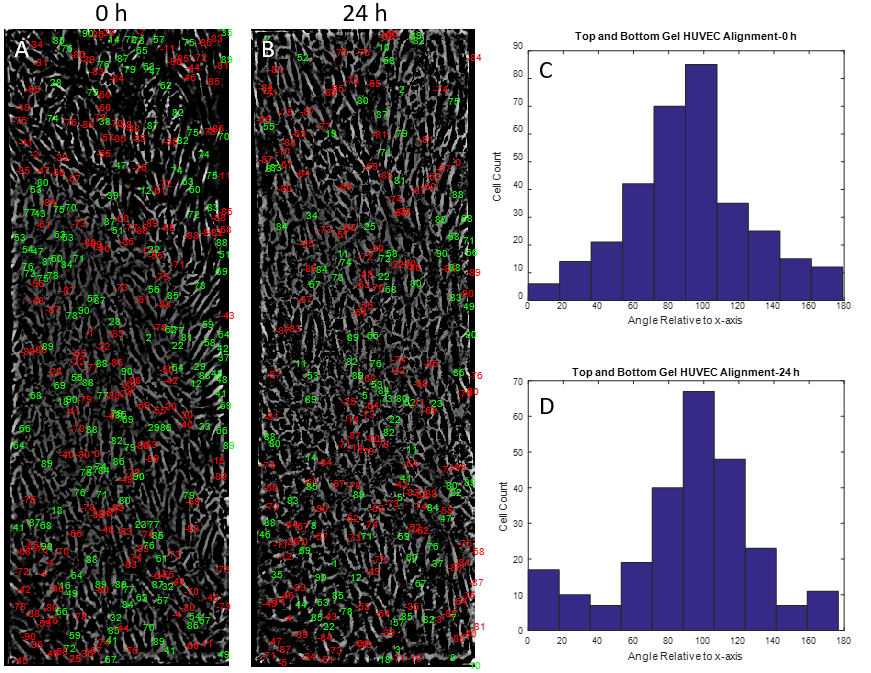
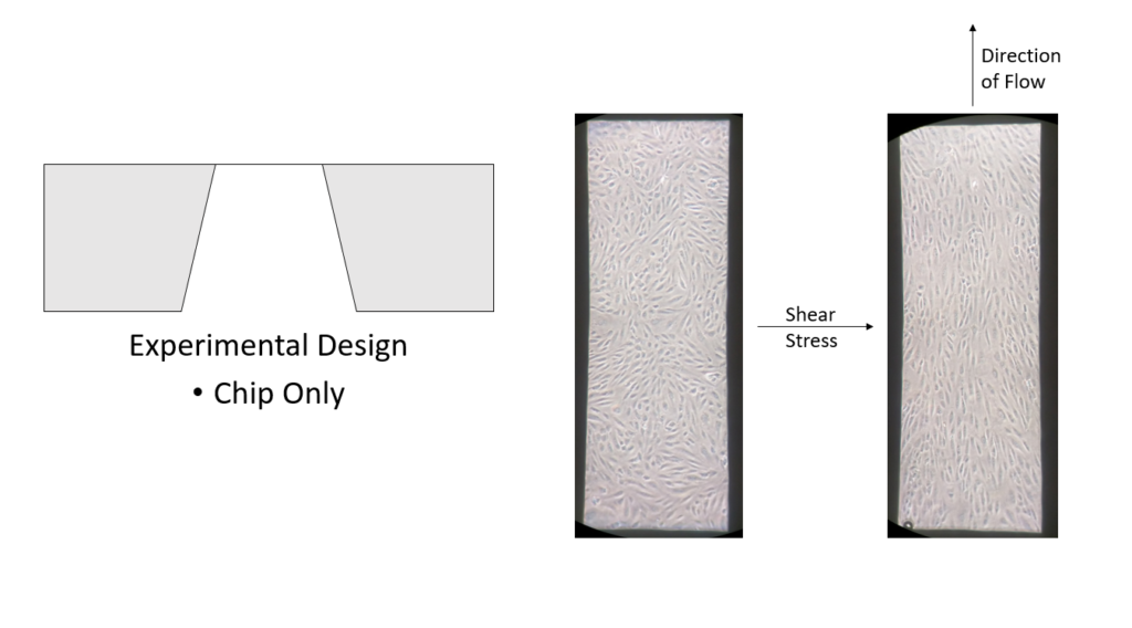
The mechanobiology behind endothelial cells has been extensively studied in recent years. Shear stress as well as substrate stiffness have both been shown to influence endothelial cell signaling and morphology in vitro [1,2]. However, the combination effect of both shear stress and substrate stiffness on endothelial cell function has not been elucidated to date. Reinhart-King et al., 2008 concluded that substrate stiffness and shear stress may influence endothelial cell function, but any results involving endothelial cell alignment were insignificant. Preliminary data produced in the McGrath lab showed that HUVECs cultured on rat tail collagen I gels atop NPN chips did not align under shear stress (Figures 1,2). As expected, however, HUVECs clearly showed alignment under shear stress atop NPN chips alone (Figures 3,4,5).
Top and Bottom Gel
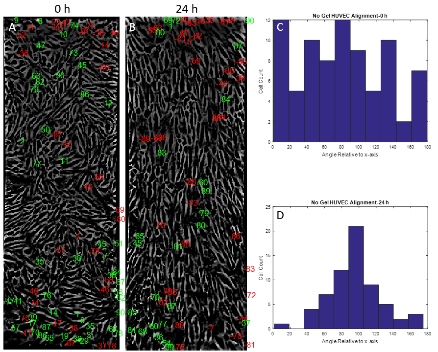
No Gel

These results brought up the interesting hypothesis: Endothelial cells do not align under shear stress when cultured on a collagen gel. The experiments performed for my rotation project were designed to further strengthen this hypothesis and propose a future direction in which this hypothesis may evolve.
-Methods
A microfluidic device was assembled containing a NPN chip with a microflow channel on the top and bottom side. The channels allow for cell culture and media supplementation without having to disassemble the device. A peristaltic pump and media reservoir can be attached to the microfluidic device in circuit to allow for shear stress applications in a more in vivo like environment when compared to the standard open cell culture flask. (Figure 6). The microfluidic device used for a majority of the experiments performed during my rotation was made with a accessible bottom channel in which a gel was added; this allows us to observe the potential effects of rat tail collagen I gel on the underside of the NPN chip on which the HUVECs are cutltured. Once the gel was polymerized, HUVECs were cultured on the gel free top side of the NPN chip and left to culture until confluent (~24 h). The cells were then subjected to 10 dyn/cm^2 shear stress for 24 h. Images were taken at multiple time points throughout culture and shear stressing.
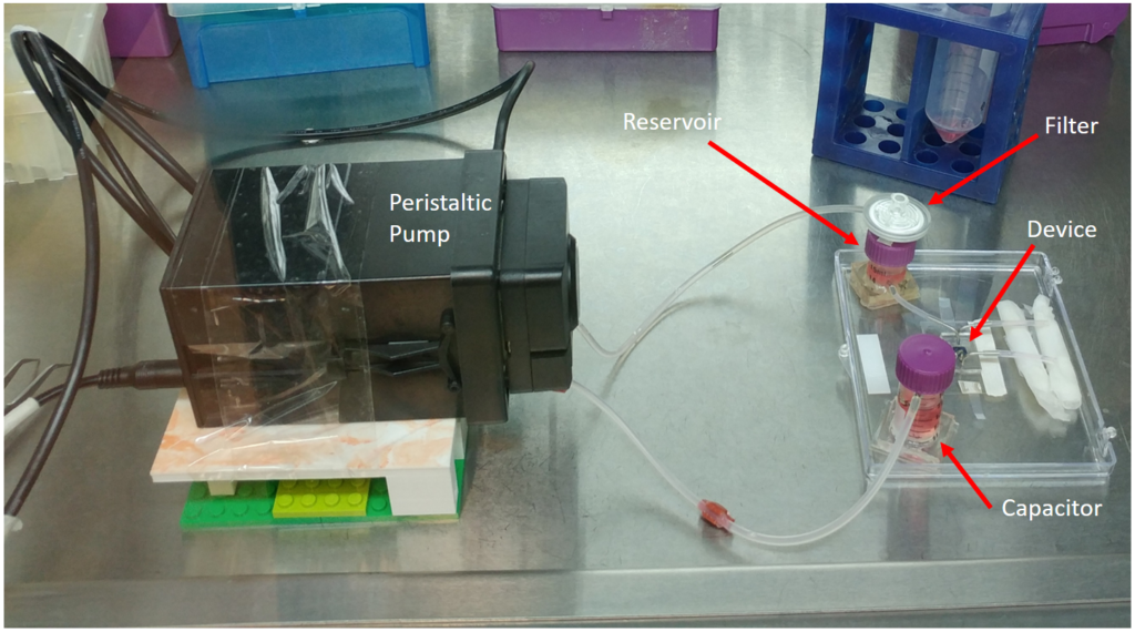
circulation while the capacitor steadies flow across the membrane.
-Results
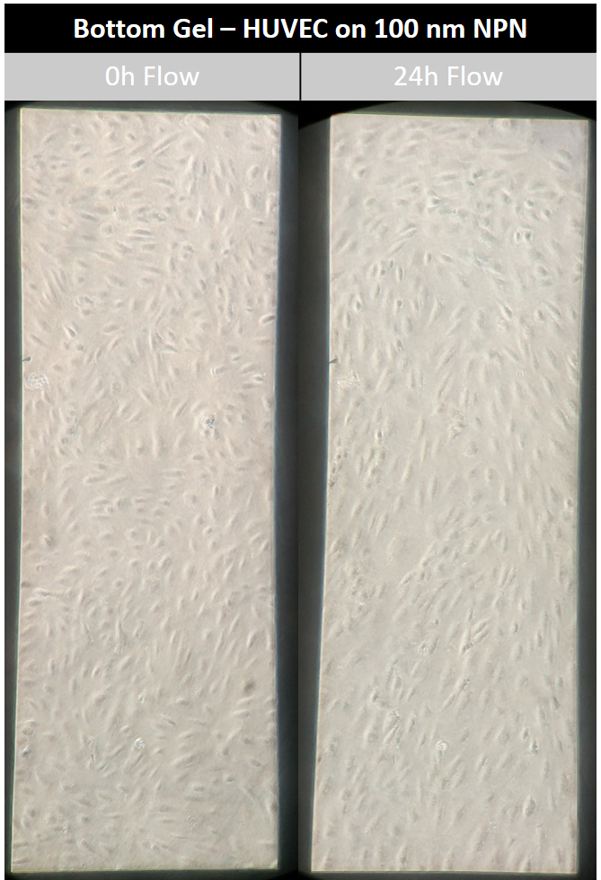
Shear Influenced Alignment of HUVECs on NPN Chips
The rat tail collagen I gel on the bottom side of the NPN chip seemed to have little to know effect on HUVEC alignment (Figures 8,9,10). HUVECs aligned with distinct capacity under in vivo analogous shear stress. The use of a nanothin membrane allows for cells cultured on one side to receive chemical ques introduced on the other side. In this case, it allows us to eliminate the mechanical effects of a low modulus collagen gel without eliminating any possible chemical influences. Therefore, the results presented here suggest that chemical influences presented by the collagen gel are not participating in the phenomenon observed when endothelial cells were cultured on the gel directly.


Confirming Shear Calculations
One major concern with the microfluidic system used is the unpredictability of the fluid flow through the channel. Mathematically, we can take the volumetric flow rate outputted by the peristaltic pump and calculate an expected shear force that the HUVECs will experience. However, a simple shear calculation experiment is necessary to confirm or dispute our mathematical claims.
To begin, a solution of fluorescent 1 um polystyrene beads were placed in the complete media used for HUVEC cell culture, and left to mix for 30 mins. The mixing allows for BSA coating of the beads in order to prevent substantial sticking of the beads to the collagen gel surface in the device. Next, the device was assembled with rat tail collagen type I gel on the top and bottom sides of a 100 nm NPN chip. Similar to the set-up pictured in Figure 6, the pump circuit with the device was assembled and the media solution was pumped through the device. Using fluorescence microscopy, a video of the polystyrene beads under flow was recorded (on a focal plane as close to the gel surface as possible) for around 10 seconds. Using Matlab, a single particle in focus was tracked over the course of 5 frames and a volumetric flow rate was obtained (Figure 11).
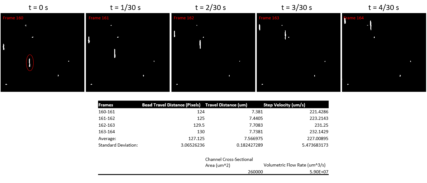
Using the formula for shear flow through a slit:
τ=6Qμ/(wh^2 )
A shear at the surface of the gel of about 0.093 dyn/cm^2 was calculated. The expected shear at this level is around 6.5 dyn/cm^2.
What was failed to be taken into account, however, is the laminar flow regimen that is exaggerated by the micro structure of the device. The next step would to repeat the experiment performed here at multiple heights within the channel to obtain an average volumetric flow rate and thus an expected shear value experienced by the HUVECs. It is also important to note that the videos obtained previously were shot at too low of a frame rate to capture the fastest beads (this is according to a simple back calculation using the pump volumetric flow rate). In order to account for this, the future experiment should be shot at 60 FPS at 20x magnification.
-Conclusion
Since the chemical influences of collagen I has been eliminated from our previous hypothesis, the next logical hypothesis would be that endothelial cells do not align in response to shear stress when culture on compliant substrates in vitro. This is an interesting hypothesis, as it directly conflicts what happens in vivo. The first future direction of the project is to finish shear calculation experiments. If shear calculations come out as expected, the next direction would be to repeat these experiments at various substrate stiffnesses to observe when a switch occurs from inhibiting to promoting cell alignment. There is also potential for improving the microfluidic device for sustained cell culture as many cultures did not appear healthy past 48 hours (Figure 12).