Cracking the KODE: Dialing in KODE Surface Coatings and the Beginnings of Chemical Capture
Since precision printing FITC KODE molecules into the windows of our 3 slot chips I have begun testing both the uniformity and the functionality of surface coatings of these molecules. In pursuit of coating uniformity I have tested several different methods of surface coating to determine which method provides the greatest uniformity. In this same regard I have also coated varying sized slits in an attempt to determine whether or not sidewall coating within slits can be achieved. To test KODE coating functionality we first attempted to block staphylococcus aureus from binding to the surface of glass slides. After this we attempted to capture fluorescent streptavidin coated beads on biotin coated chips both statically and under flow. Success with particle capture has led us to begin testing with application based antibody capture. Altogether these experiments paint a better picture of the potential for using KODE as a functional surface coating.
Uniformity of KODE Coatings
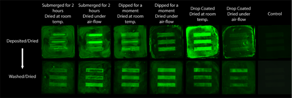
We began testing the uniformity of KODE molecules by using fluorescent FITC KODE (A typical FSL construct with FITC as its functional head). As described in Figure 1 below I tried three different deposition methods (submerging for 2 hours, Dip-coating, and drop-coating) and two different drying methods (at room temperature and under nitrogen flow) using a 50 uM solution of the molecules. Each chip was imaged before and after washing with DI. With varying uniformities depending on which methods were used to coat and how the molecules were dried, we decided that dip-coating and drying under air flow gave us the best surface coating uniformity. Therefore we used this method moving forward when doing any KODE surface coatings.
PEG KODE as an Anti-adhesion Coating
Our next experiment was done to determine the functionality of KODE by attempting to capture Staph A with PLL and then block it with PEG KODE. The idea was that PLL coated surfaces would promote adhesion of staphylococcus aureus while a PEG coating would prevent the binding of staphylococcus aureus. Unfortunately as shown in Figure 2, this was not the case. Both the PLL coated surface and the PEG coated surface seemed to promote staphylococcus aureus adhesion. This led us to believe that either PEG was not as good at blocking the adhesion of bacteria as we thought or the FSL KODE construct may be behaving differently than regular PEG.

Determining Slit Wall Surface Coating
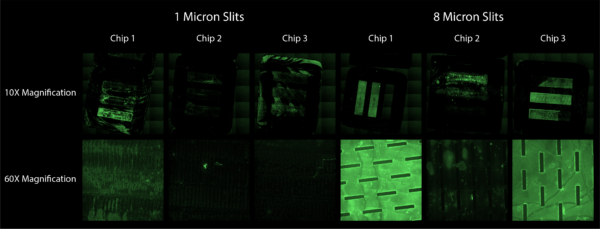
Moving forward with the analysis of our KODE coatings, we wanted to determine whether or not KODE molecules were coating the interior of the slits of our chips or if they were just coating the top and bottom of each window of our chips. I attempted to figure this out by coating 1 micron and 8 micron slit chips in 50 uM FITC KODE and taking z stacks of our results. Single plane results are shown in Figure 3, showing that uniform coatings were more successful on 8 micron slit windows as opposed to 1 micron slit windows. Figure 4 shows a flyover animation of one of the 60X z-stacks of the 8 micron chip 3.
Conclusions
From this work we are encouraged to continue working with KODE molecule surface coatings. The next post will outline our experiments with Biotin KODE capturing fluorescent Streptavidin coated beads.