hToC Modular Approach
Background:
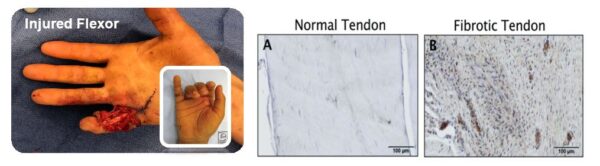
The human Tendon-on-Chip (hToC) spans collaboration between the Center for Musculoskeletal Research (CMSR) at the UR and the McGrath lab to develop an in vitro platform to study inflammation, fibrosis, and cell-cycle regulation in fibrovascular tendon healing. Interaction between the blood-tendon-barrier (BTB) is fundamental to the investigation of this pathology as part of the wound healing cascade. The two cell types incorporated into the model are human umbilical vein endothelial (HUVECs) to simulate the vascular barrier and primary tendon fibroblasts as the dominant cell type in tendon tissue. In addition, there is a vasculature: tendon tissue aspect ratio of 1:5 that must be maintained for physiological relevance. Also important is the fibroblast’s requirements of directional strain to align uniaxially and form a strong tissue. This has been achieved in in vitro models by providing anchors in the form of ceramic screws, steel rods, or thick PDMS posts.
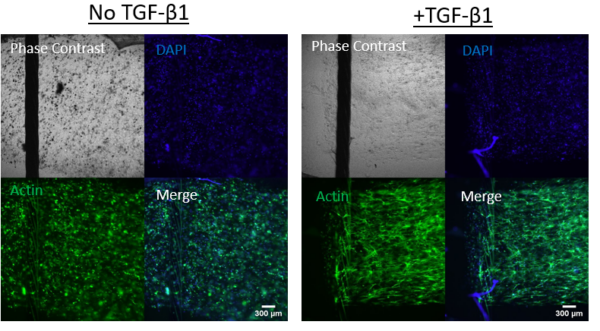
To produce a successful platform for this application, the model must represent the in vivo 3D tissue environment of the native tendon which has been achieved by using a type-I collagen hydrogel. Some additional metrics for the platform also include the ability to enable live microscopy, allow for paracrine crosstalk between the tissues and permit differentiation of primary tendon fibroblasts into activated myofibroblasts.
Initial Approach:
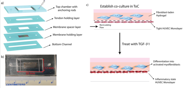
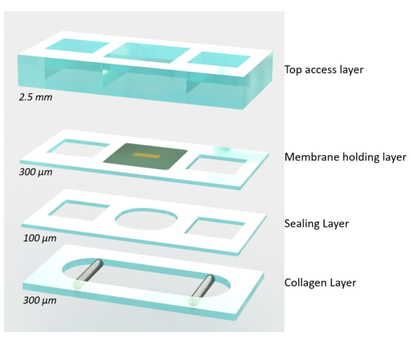
The initial approach was to design a platform with a bottom channel to house the vascular cells which allowed for shear priming of the cell monolayer. The top compartment was composed of a well that houses a hydrogel holding layer that spans in the x-direction and attaches around two tangential steel rods. An 11 X 5.4 porous membrane separates the two tissues.
All the requirements for the platform were met with this model, some more easily than others.

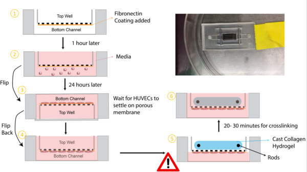
The main drawback to the model was that the assembled device required different orientations for seeding each tissue. To settle the HUVECs on the membrane in the bottom channel the device must be flipped during the settling time and media introduced into both the top and bottom compartment. On the other hand, the hydrogel requires a dry top chamber to control its shape. Unfortunately, the required media in the top well during the vascular seeding phase prevented the hydrogels to be uniformly introduced and altered the hydrogel composition if large amounts of media were still in the chamber or profuse through the membrane.
In case this is pondering in your head:
- Why not switch the locations of the tissues? (hydrogel in the bottom and HUVECs in the top?
- A couple of reasons actually. First, this device is pre-assembled on a non-permeable glass slide which means we need to introduce the collagen into a closed channel. We initially tried this and quickly found that the hydrogel has a difficult time crosslinking in a closed channel (crosslinking time took up to 3X longer). The hydrogel also does not crosslink uniformly, and the presence of bubbles and the hydrogel receding caused large variations in the hydrogel shape. Other groups have been successful in introducing collagen into channels, yet it is usually accomplished through suction into the channel or a constant pressure source until complete crosslinking occurs. Therefore, we opted to seed the collagen in an open well.
- Why not seed the collagen first?
- The required flipping for the HUVECs to settle on the membrane causes the hydrogel (which is in suspensions aside from the anchoring points) to hang, causing additional stress to the cells and in some cases rupture of the hydrogel.
Modular Approach:
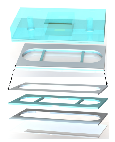
As you can probably see, a clear solution following the success of the µSiM, it was evident that these issues could be addressed through a modular approach. By having two separate components we could seed both tissues separately and join the tissues once they have matured and crosslinked.
So, again starting from what we have learned from the µSiM it was decided to start from this platform and adapt it to fit the hToC requirements. This would also minimize manufacturing time with ALine as they would not need to make drastic alterations to the current µSiM. The modularity also allows us to move the hydrogel into the bottom channel as we can keep the top of the channel layer open until we unite the two components. The main difference between the current µSiM is the addition of anchoring supports in the bottom channel, and the riddance of the tapered ends of the channel. Where the top component remains the same, increasing the advantage of modularity between the models. Additionally, we are still able to meet the 1:5 tissue ratio as we will be using the single slot 5.4×5.4 membranes and slightly increasing the area of the channel.

We are currently waiting for ALine to get some prototypes of this bottom component to perform some testing, so stay tuned!