Fabricating Thin Polymer Coatings to Study S. Aureus Durotaxis – PUA Optimization
Introduction
The work in this post explores the hypothesis that durotaxis affects the invasion of S. aureus into the osteocyte lacuna-canicular network (OLCN). To address this hypothesis, we modified the µSiM to enable the independent tuning of pore stiffness, ranging from those of soft-tissues to that of silicon nitride (~10X stiffer than bone). More background information related to this study can be found in Michael’s post here.
We aim to coat the flat side of 0.5 μm hole pore chips with polymer and etch through the trench side of these coated membranes. This will result in a soft surface for S. aureus to crawl through that mimics the porous membrane. Specifically, we focused on optimizing a polymer layer of polyurethane-acrylate (PUA) as well as polydimethylsiloxane (PDMS). As discussed in a previous post, both of these polymers have a young’s modulus that is a factor of 1000 smaller than that of bone. Thus, they will provide a soft surface to study S. aureus durotaxis.
Overall Approach
- Spin coat a layer of a soft polymer (PDMS or PUA) on 0.5 μm hole pore chips.
- Etch (via reactive ion etching) through the backside of the chip to create pores in the polymer.
- Chip acts as a shadow mask to allow etching of polymer through chip windows.
- We want an anisotropic etch to achieve uniform pores in the polymer layer.
- Measure polymer stiffness with AFM.
- Analyze layer thickness with SEM.
Results: Spin Coat and Etching Optimization
First PUA Spin Coating Attempt
We began by spin coating polyurethane–acrylate (PUA) provided by Dr. Alexander Shestopalov on 3 window 0.5 µm hole pore chips. Since our goal is to achieve a 1 µm-thick layer, we tested the following 5 spin coat recipes:
- Step 1 -500 rpm for 120 seconds, Step 2 – 10 seconds of 500 rpm and 60 seconds of 2000 rpm
- Step 1 – 2000 rpm for 10 seconds, Step 2 – 4000 rpm for 60 seconds
- Step 1 – 2000 rpm for 10 seconds, Step 2 – 5000 rpm for 60 seconds
- Step 1 – 2000 rpm for 10 seconds, Step 2 – 6000 rpm for 120 seconds
- Step 1 – 2000 rpm for 10 seconds, Step 2 – 6000 rpm for 120 seconds
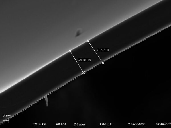
The deposited PUA was cured using a UV light for 30 minutes. Despite the differences in recipes, we consistently saw a thickness of around 8-9 µm.
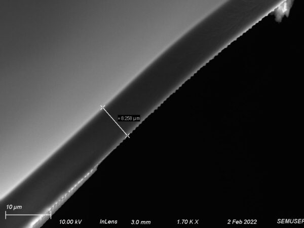
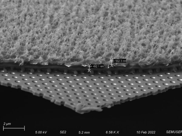
An important finding from these images is the presence of “buttons”, as shown in the image below. This additional thickness should be accounted for in our backside etching recipe to achieve a complete etch through the polymer. In the image below, the buttons add an extra 500 nm of material.
Second PUA Spin Coat Attempt
After the first spin attempt, we experimented with 6 more recipes at higher speeds and varying volumes to get a smaller thickness. We also used a more precise droplet volume with a pipette.
- Step 1 – 2000 rpm for 10 seconds, Step 2 – 6000 rpm for 300 seconds, Deposit 10 uL
- Step 1 – 2000 rpm for 10 seconds, Step 2 – 8000 rpm for 300 seconds, Deposit 10 uL
- Step 1 – 2000 rpm for 10 seconds, Step 2 – 8000 rpm for 300 seconds, Deposit 5 uL
- Step 1 – 2000 rpm for 10 seconds, Step 2 – 6000 rpm for 300 seconds, Coat chip and paint to edges with 25 uL, remove excess PUA with pipette
- Step 1 – 2000 rpm for 10 seconds, Step 2 – 6000 rpm for 300 seconds, Coat chip and paint to edges, remove excess PUA with pipette
- Step 1 – 2000 rpm for 15 seconds, Step 2 – 6000 rpm for 300 seconds, Deposit 15 uL while spinning in first step
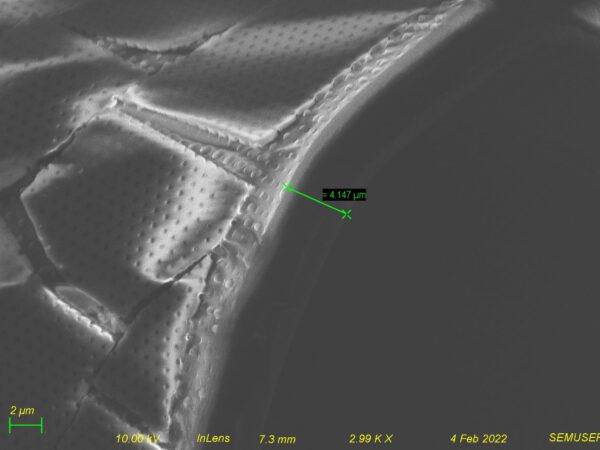
The deposited PUA was cured using a UV light for 30 minutes. Although thinner at around 4 µm, the spin recipes #1 and #2 did not result in the desired thickness, as shown below. Spin recipe #4, which only deposited 5 uL, did not provide enough volume for the polymer to reach the edges of the chip.
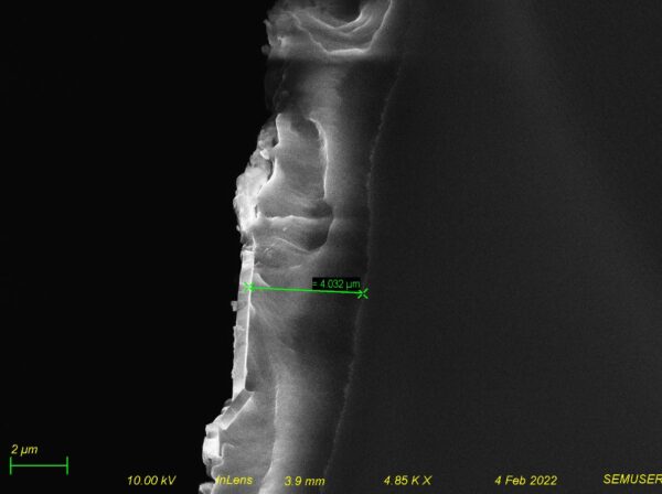
In addition, removing excess PUA (as described in spin recipes #4 and #5) did not decrease the thickness.
We decided that instead of trying to spin the polymer down to 1 µm thickness, we will instead create a protocol to coat the chips at a reproducible thickness and then etch them flat side up to 1 µm.
Third PUA Spin Coat Attempt (with Etching)
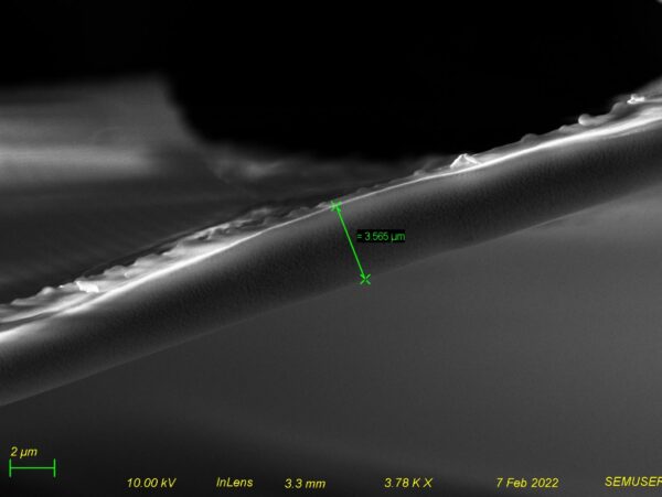
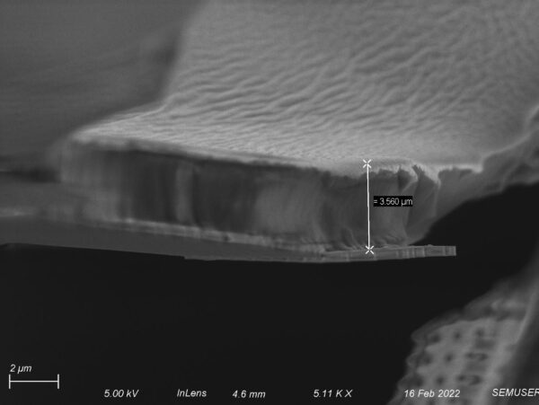
For this experiment, we deposited 25 µL PUA onto the membrane with the following spin coat procedure: Step 1 – 2500 rpm for 10 seconds, Step 2 – 7500 rpm for 300 seconds. The deposited PUA was cured using a UV light for 30 minutes. The layer thickness is 3.5 µm, as shown below.
Next, we etched the chips using an oxygen/argon etch at 12.5 sccms each with 150 W forward power for 10 minutes. The etching resulted in a fiber-like polymer structure and did not leave behind a consistent layer.
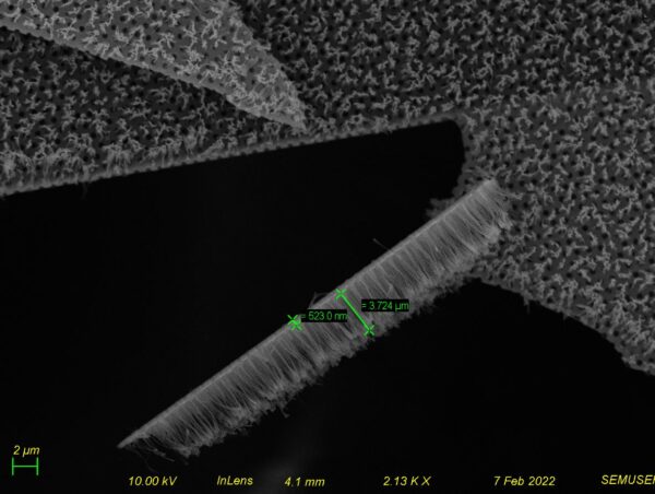
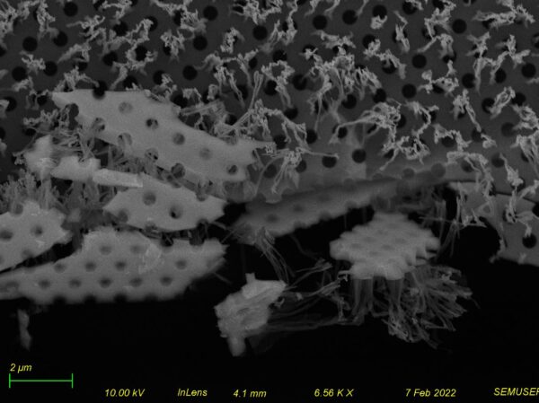
Based on these images, we attempted a less aggressive etch.
Second PUA Etching Attempt
From this experiment onward, we employ the following spin recipe, as we are able to get a reproducible ~4.5 µm thickness: Drop 25 uL onto the membrane, Step 1 – 2500 rpm for 10 seconds, Step 2 – 7500 rpm (true speed around 8200) for 300 seconds. The deposited PUA was cured using a UV light for 30 minutes
The following etch recipes were tested:
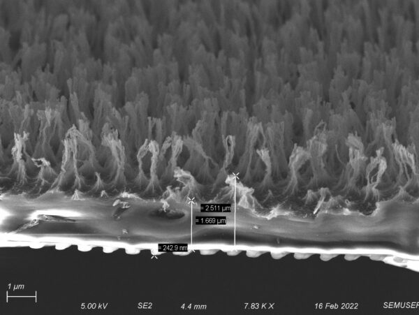
1. Oxygen/argon etch at 25 sccms each with 150 W forward power for 5 minutes. This recipe created interesting “grass” structures that could potentially be useful for anti-fouling applications. We believe this occurred because the etch was too directional.
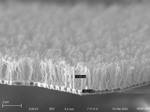
2. Oxygen/argon etch at 25 sccms oxygen and 50 sccms for argon with 150 W forward power for 5 minutes. This recipe resulted in similar grass structures, however the height is smaller at 500 nm.
Third PUA Etching Attempt
1. Oxygen/SF6 etch at 25 sccms oxygen 3 sccms SF6 with 150 W forward power for 5 minutes. This recipe did not help in addressing the grass structures, however we see a block of solid polymer below the grass.
2. Argon etch at 50 sccms for argon with 150 W forward power for 5 minutes. We decided to use an only-Argon etch, as argon can provide the most non-directional etch. This recipe resulted in a uniform layer of around 3.5 µm (compared to the unetched thickness of 4 µm). From this, we calculated an etch rate of 100 nm/min.
Fourth PUA Etching Attempt
1. Based on the previously estimated etch rate of 100 nm/min and an average coating thickness of 4 µm, we ran only argon etch at 50 sccms with 150 W forward power for 30 minutes to try and achieve a 1 µm thickness. Since a 30 minute etch time is relatively long, the chamber got very warm and may have melted the polymer, as shown below.
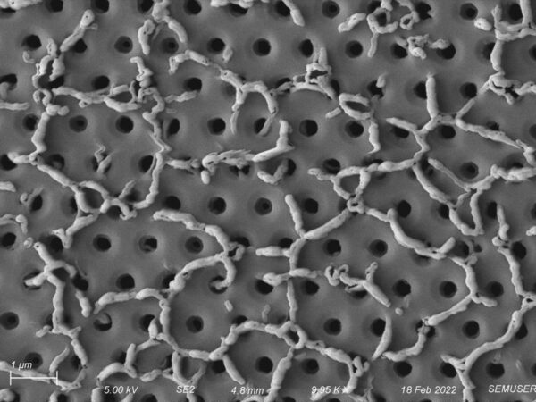
2. Instead of a pure argon etch which proved to be too time-consuming with adverse effects, we also attempted an oxygen/argon etch at 25 sccms oxygen and 50 sccms for argon with 150 W forward power for 4.5 minutes followed by an argon etch at 50 sccms with 150 W forward power for 5 minutes. This recipe also appeared to be too aggressive, as there was little polymer left on the surface.
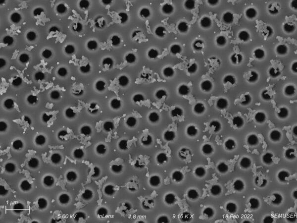
Fifth PUA Etching Attempt
We had previously tried an only argon etch, which was the only recipe that succeeded in having no grass structures. Oxygen can be used as a de-scumming etch, therefore we attempted an oxygen etch at 50 sccms with 150 W forward power for 5 minutes. We found it had the same effect as the 30 min only argon etch.
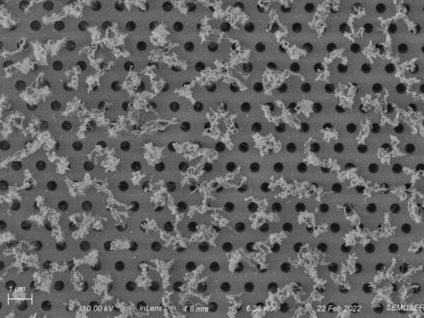
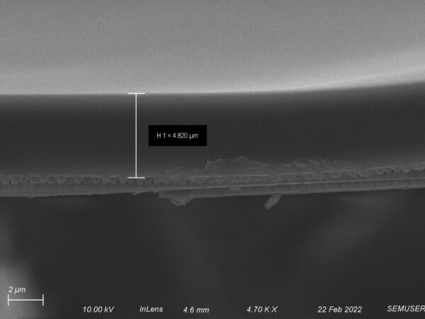
We also tried masking part of the chip during the etch to get a more accurate etch rate, but instead of a clean step from the etched vs. unetched portions, it was more of a gradient change. However, we were able to further confirm that we are getting a uniform thickness from the spin process by measuring the thickness of the masked portion.
Sixth PUA Etching Attempt
1. Oxygen/argon etch at 25 sccms oxygen and 50 sccms for argon with 110 W forward power for 4.5 minutes. Then oxygen etch at 50 sccms with 150 W forward power for 2 minutes as a polishing step.
This recipe resulted in the opposite of what we expected to happen: although this recipe included the extra oxygen step for polishing, it left more grass. The block is close to 1 um thickness, but the grass layer remains.
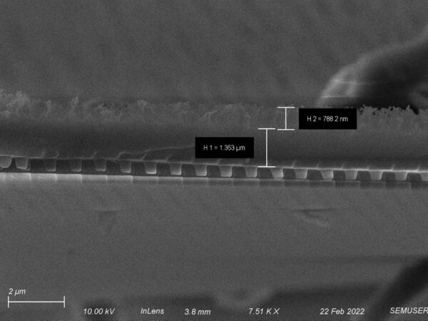
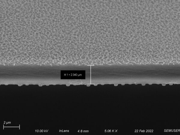
2. Next we removed the oxygen polishing step and performed an oxygen/argon etch at 25 sccms oxygen and 50 sccms for argon with 110 W forward power for 4.5 minutes. Note same thicknesses from this and the previous recipe, but differences in grass:block ratio. This recipe shows promising results and thickness with some remaining surface roughness, although the roughness shouldn’t significantly affect S. aureus propagation.
PDMS Backside Etching Attempt
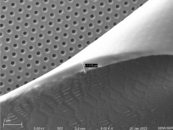
We briefly attempted the backside etching procedure with PDMS. A 10:1 monomer:hardener PDMS was prepared and degassed before depositing onto the membrane. The deposition volume was a droplet roughly the size of the membrane. The following spin coat procedure was used: step 1 – 2500 rpm for 10 seconds, step 2 – 10000 rpm for 300 seconds. This was cured via baking on a hotplate at 210 degrees Celsius for 10 minutes creating a roughly 1 µm thick coating of PDMS, shown below. We can also see the layer of PDMS peeling away from the membrane.
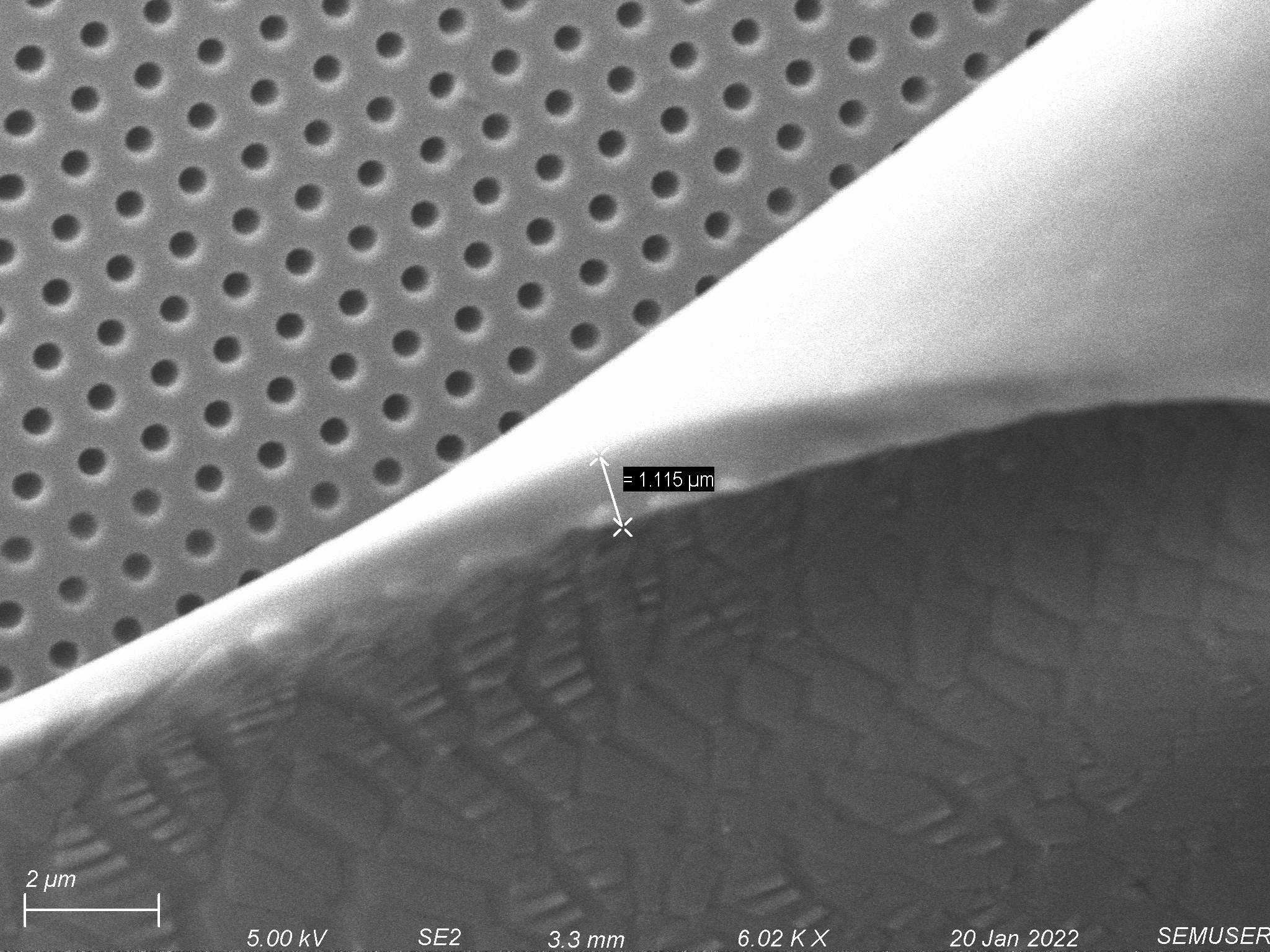
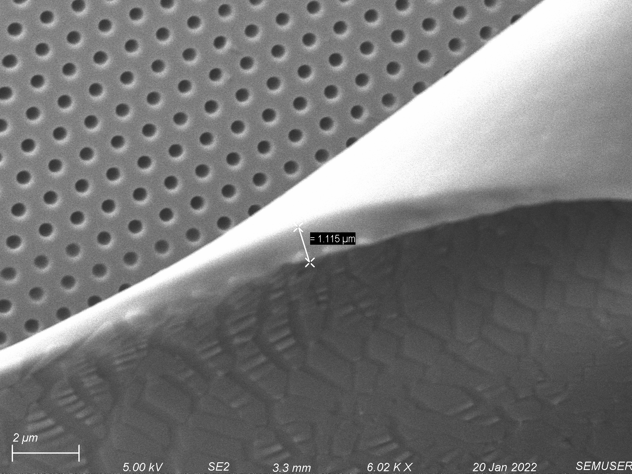
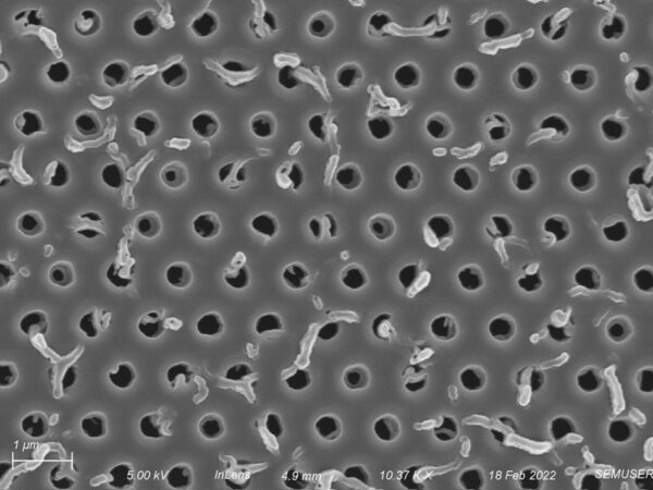
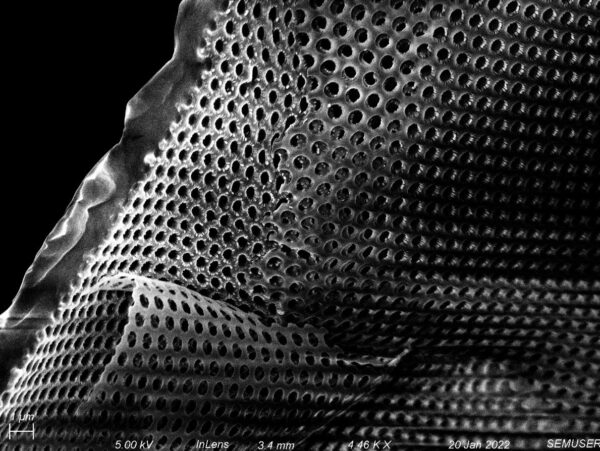
We etched the PDMS with an oxygen/sulfur hexafluoride mixture with both at 15 sccms and 125 W forward power for 10 minutes. In the below image, we can see that the etch created pores in the PDMS, with the membrane peeling away from the polymer layer.
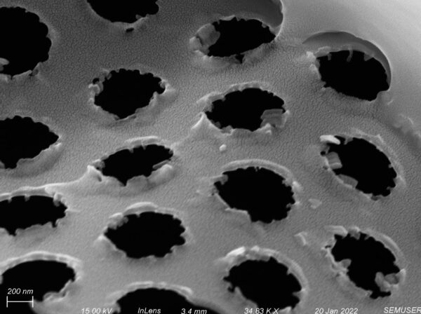
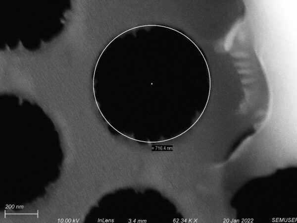
Looking up close at the pores, we can see that they have jagged edges and are blown out, as the diameter is closer to 700 nm (versus the expected 500 nm). Thus the etch recipe should be adjusted to achieve a more anisotropic pore.
Future Work
- Apply backside etching procedure to optimized PUA layer.
- Optimize backside etching procedure for PDMS.