TEER Measurements First Attempt
After integrating my thin film electrodes into the layer stack of the BBB device, I want to make some TEER measurements.
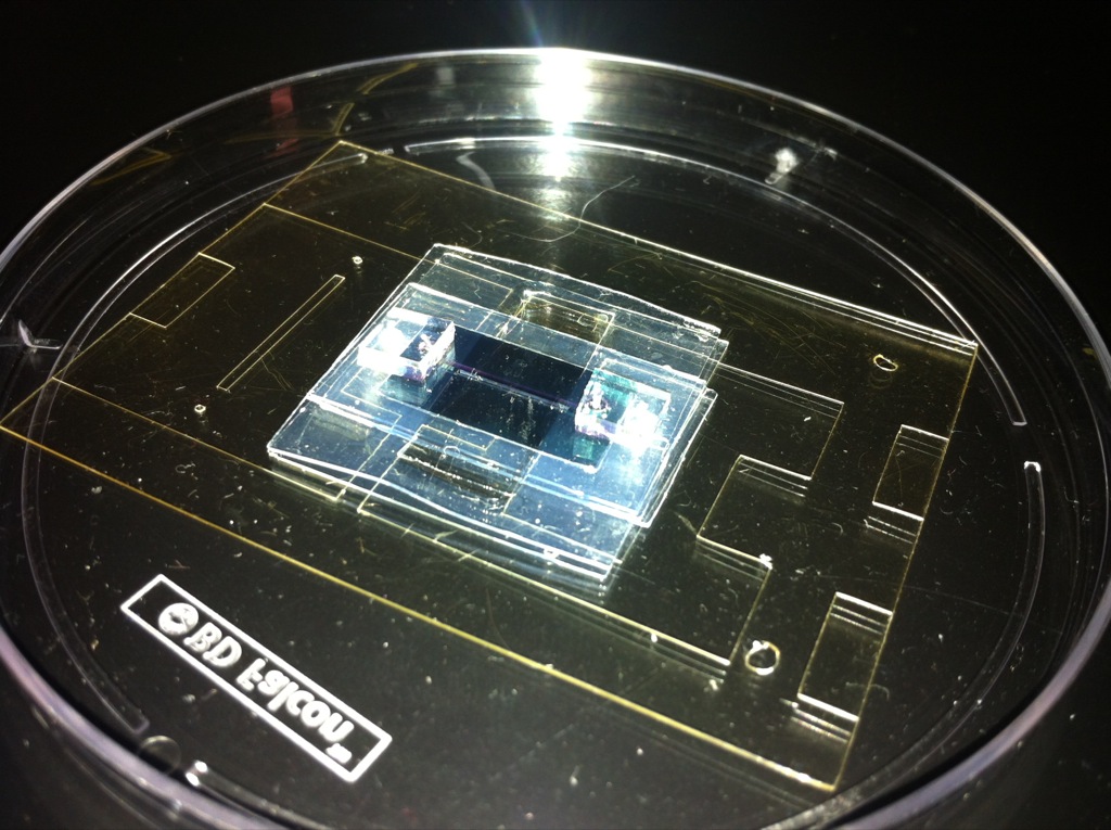
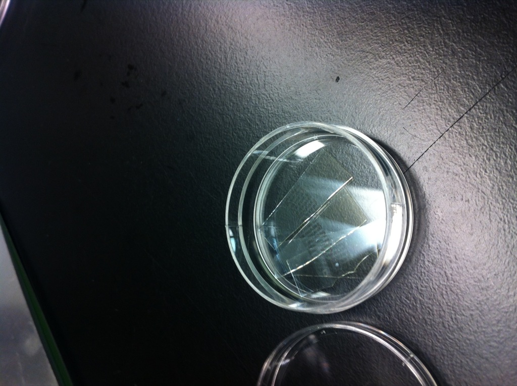
I stripped off the well-plate attachment off of the TEER tool, exposing the individual leads.
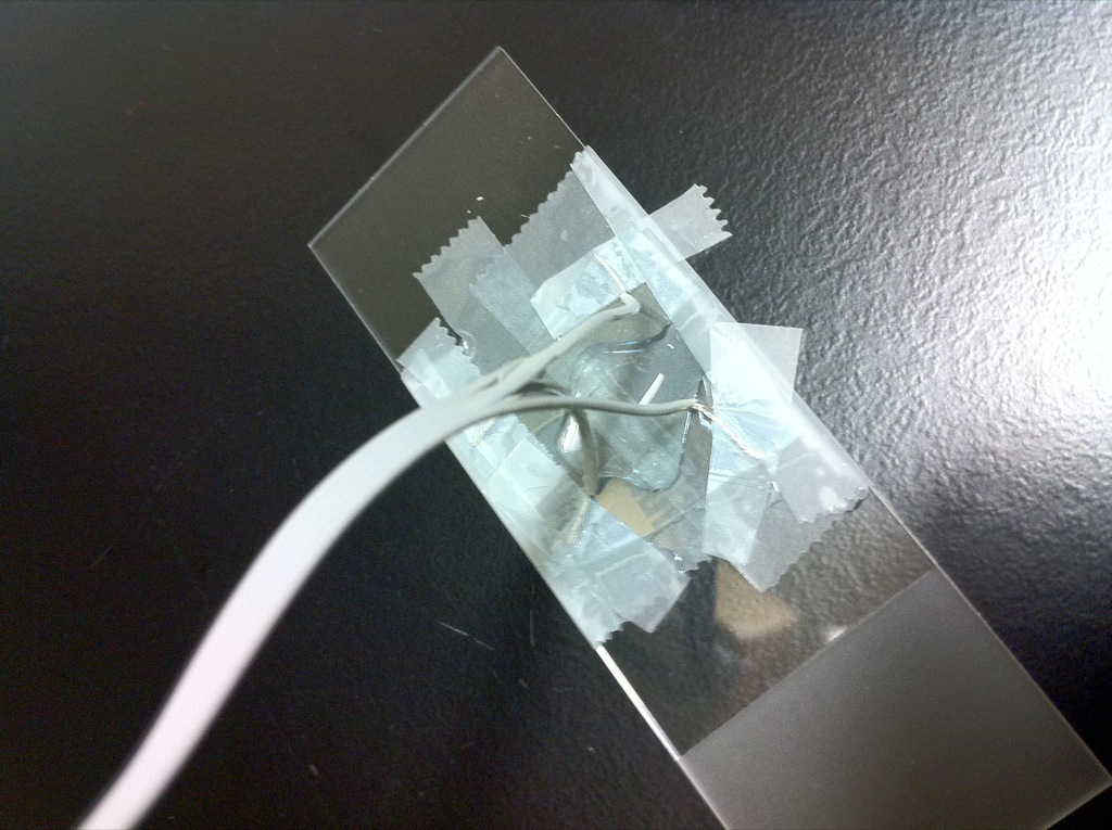
To test that the circuit functioned properly, I placed the leads in DI water and then Tap water, producing an open circuit (greater than 20 kohms) and a short circuit (~300 ohms) respectively. The leads are then attached to the sides of the BBB device, making contact with the inner surfaces of the glass coverslips (where ITO has been deposited). If the leads are not immersed, the TEER tool will buzz with warning. I then confirmed that my thin film coverslips were conductive enough to produce a reading by “breadboarding” the circumstances in the chamber. I assumed that the both channels are completely wetted, and that no liquid comes into contact with the individual electrode leads (which would cause a short circuit, bypassing my ITO films entirely). My expectation was that DI water would create an open circuit (greater than 20 kohms) and Tap water would cause a short between the two ITO resistance pads (around 6 kohms, 2x 3kohm pad to finger resistances).
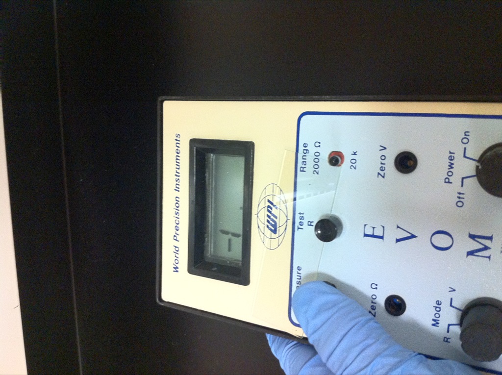
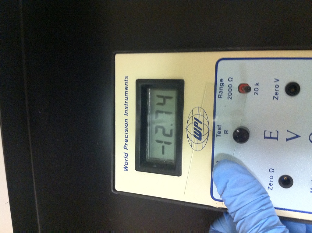
My results confirm that the circuit works, however, I’m getting 2x the resistance I expected (each pad to finger resistance is ~3kohms). I don’t have a good rationale for why this is occurring. Intuitively, I think that because the interdigitated region was not completely wetted, this is contributing to an increase in the resistance (resistors in parallel vs resistors in series). This is an example of why it is important to lower the background resistance as much as possible.
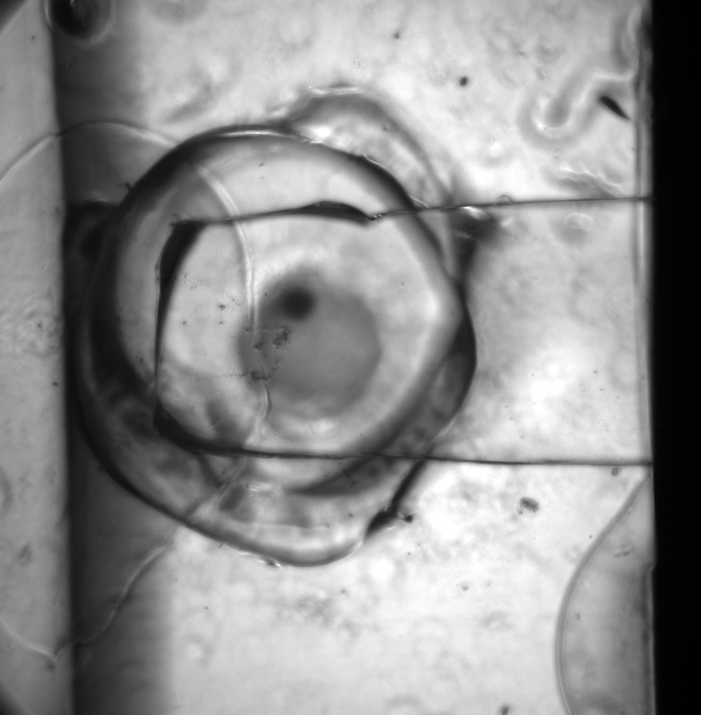
The channel itself is ruptured, so flow visualization with beads is unrealistic.
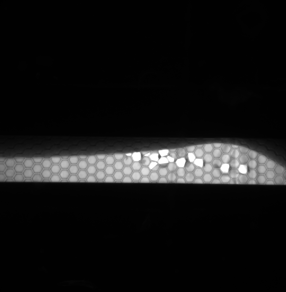
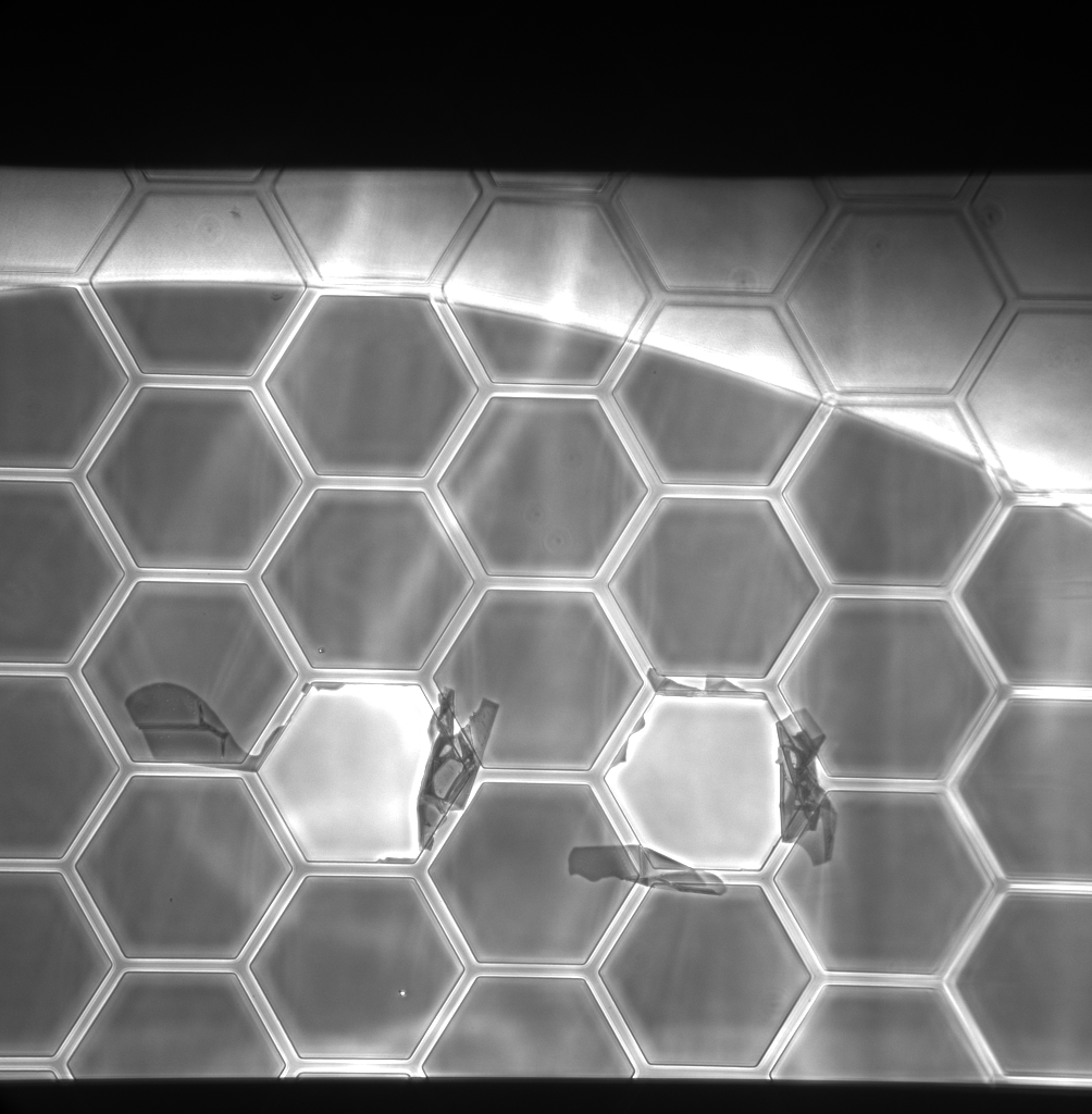
Instead, I used colored dye in Tap water to mark the indivudal channels. Red was the top channel, green was the bottom channel.
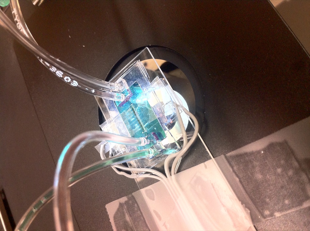
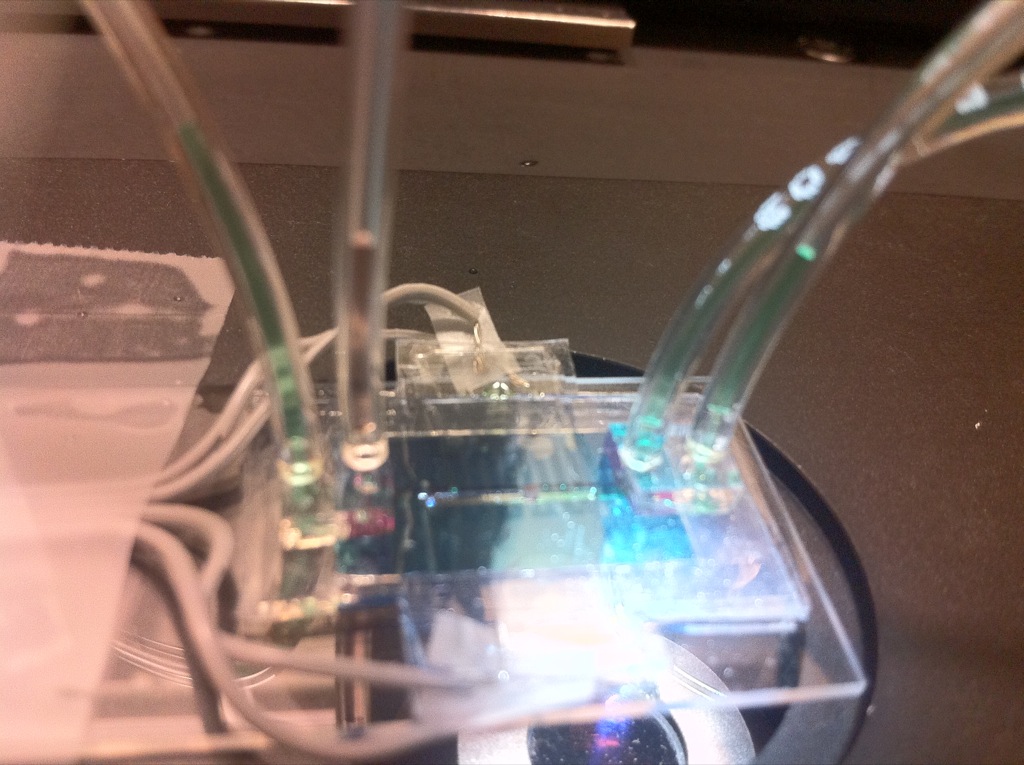
When I originally turned on the device, I got a reading of ~7 kohms, which I was expecting. However, when I flowed more fluid through both chambers, the resistance dropped to ~3.5 kohms. This puzzled me until I looked at the chamber itself.
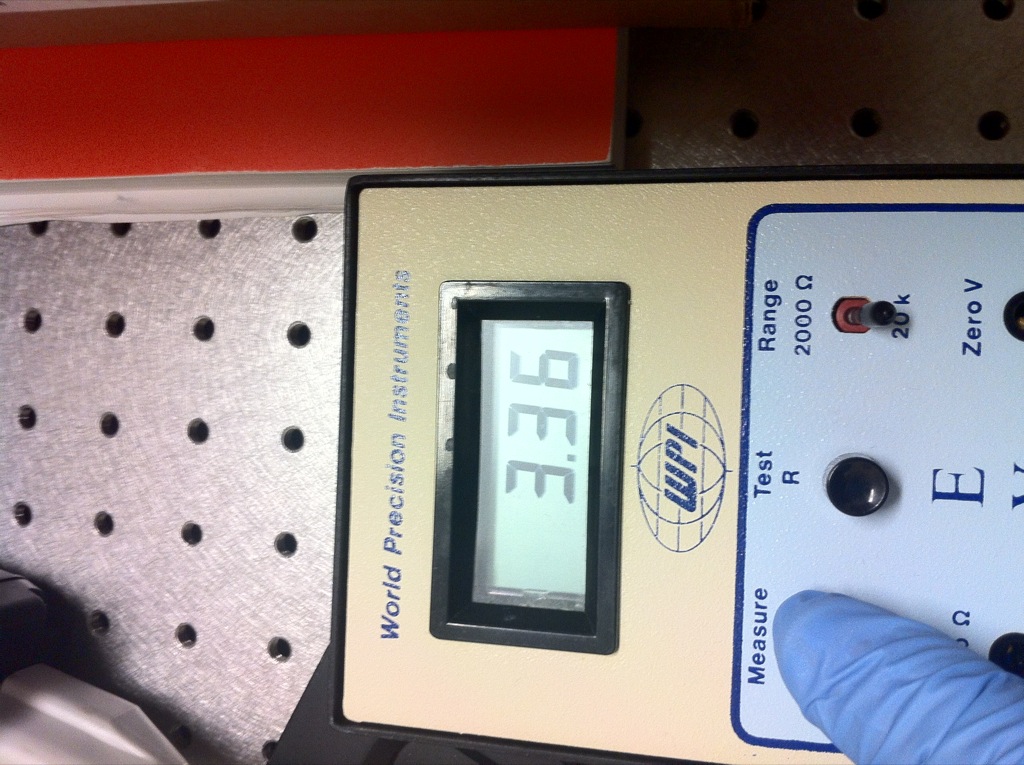
Two leaks were obvious, where the top electrode and top gasket did not seal and filled up with fluid, and then the output pdms port from the top chamber. When I measured the resistance the second time, the fluid had gone further underneath the ITO interdigitation and made contact with the ITO pad. This effectively shorted out that side, as the resistance of the pad is much lower than that of the fingers (1st time, ~3kohms+ ~3kohms = 7kohms. 2nd time, ~3kohms + ~500 ohms = ~3.5 kohms).
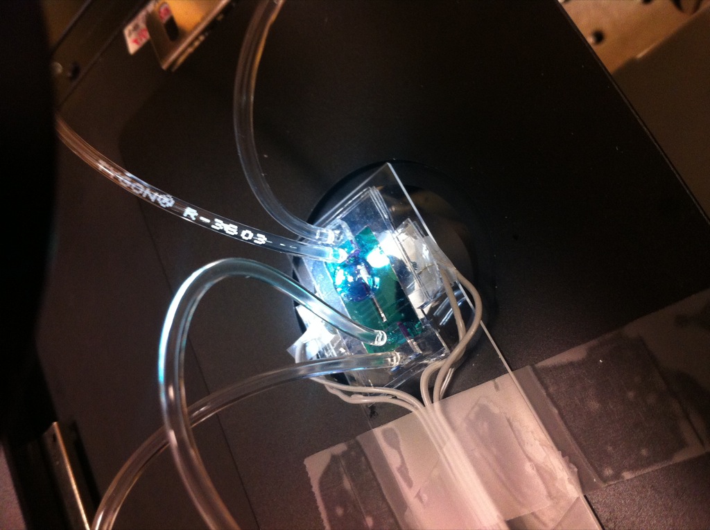
I tried to dig into this a little further by monitoring the resistance over a few minutes. There was some interesting cyclic behavior going from 3.5kohms down to 1.5kohms and back every minute or so. I don’t know what to make of this phenomenon just yet, but my intuition is that the interdigitated design may be involved.
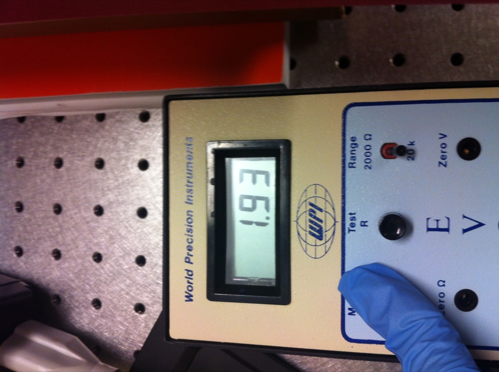
I had hoped to open the circuit again by flowing a lot of DI water into the chamber, but the clearance was so low, the TEER never really changed.The silver lining is that a successful TEER measurement can be made.
Things to improve
– Electrode embedding. The gasket was not sealed planar enough. The PDMS wicking across the electrode must be countered, as the additional PDMS film that forms introduces a height difference that is enough to create a “chamber”. May do a flip chip style embedding to counter.
-PDMS feet sealing. I think this will be fine in future iterations; I can use fresh PDMS instead of some I cured 3-months ago. Making the feet slightly larger will ensure enough of an area to bond.
– Get alligator clips to make attachment of TEER leads easier.