Micropump Data Update
After a few more revisions of the micro pump, I performed a significantly more thorough characterization. Flow rate was determined as before using a horizontal capillary of known volume and a stop watch. A extremely small thermocouple was inserted into the PDMS substrate directly adjacent to the fluid outlet channel emptying the diaphragm chamber (Figure 2). The electromagnet was driven with a constant 10% duty cycle pulse switched by a MOSFET.
| EMF (V) | Power (mW) | Thermocouple Temperature raise (°C) |
| 8.0 | 147.1 | 6.3 |
| 10.0 | 229.9 | 9.8 |
| 12.0 | 331.0 | 13.0 |
Table 1. Steady-state operating characteristics. No measures were taken to dissipate heat.
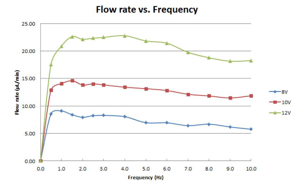
Figure 1. Tests were conducted with 13mm of head pressure and several feet of 1/16 ID tygon interfacing device.
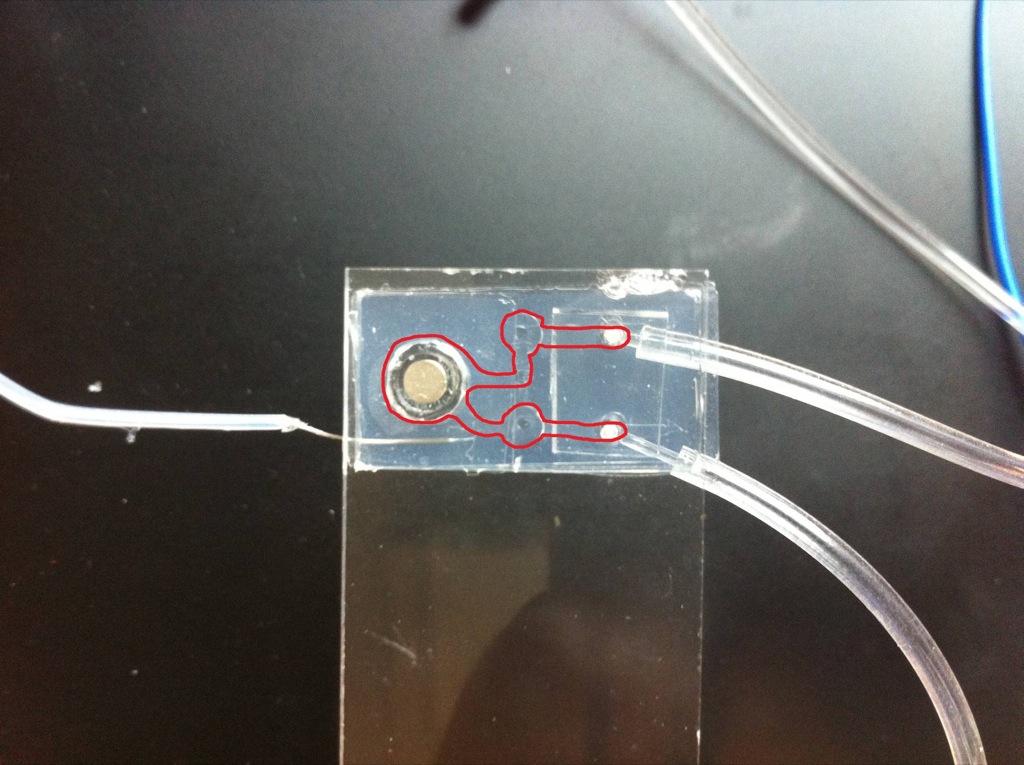
Figure 2. Channels highlighted in red. Note the type K thermocouple adjacent to the bottom outlet port.