Applying a Voltage to Silver-Coated SNM Can Change the Rate of EO
Because I’ve been having such a difficult time measuring consistent zetapotentials (a big and heartbreakingly inconclusive post on those efforts is forthcoming) I decided to use one of my silver-coated SNMs as an EO pump and see if changing the voltage applied to the membrane changed the rate of EO. And I’m very happy to report that it does!
This is pretty preliminary here, and I’m having trouble quantifying rates and taking videos on the microscope, but in this video, the following happens:
0-30s Nothing
30s – 1:30s Function generator applies ~ +/- 2V. No voltage applied to the gate.
1:30s-2:30 Function generator still running. -1.4V applied to gate.
2:30-3:30 Function generator still running. +1.4V applied to gate.
3:30-4:00 Function generator still running. No voltage applied to the gate.
4:00-4:30 Nothing.
Link for video (apparently WordPress won’t embed it. Please excuse the lame narration. Obviously the function generator is not applying alternating frequencies.)
The most obvious change comes at 2:35ish. The transision between +/- 1.4 V applied to the gate is pretty clearly changing the EO behavior, although it takes a pump cycle or two for the change to happen fully.
Here’s my setup:
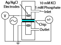
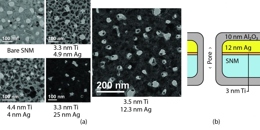
Note that the blue rectangle is the silver-and-Al2O3 coated chip, which looks like this:
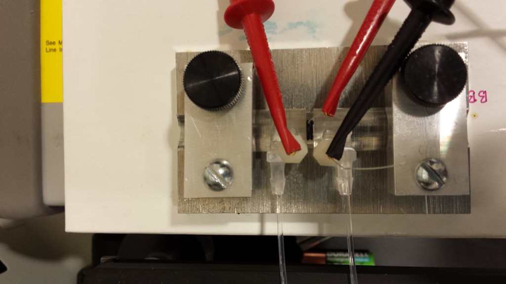
Here’s a closeup of the setup:
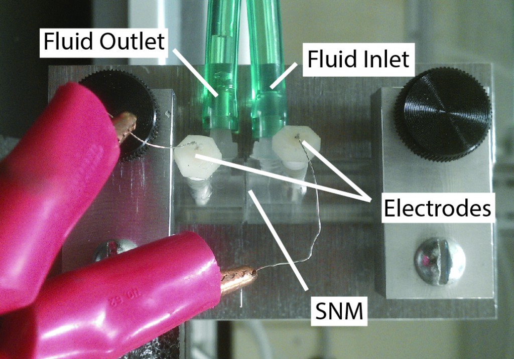
Here’s an older picture of the setup with labels:
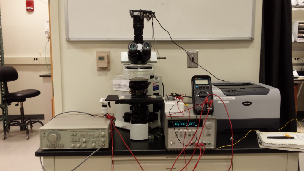
And here’s the complete setup, including a function generator (bottom left), voltage source (bottom right), voltmeter for monitoring the function generator, microscope, and the actual zeta setup.
It is possible that the alumina layer coating the silver is not thick enough, and what we’re really seeing here is voltage leaking into the membrane, and not strictly a modification of the electric field inside the pores. I can’t be sure yet. I need to repeat the experiment while monitoring the current flowing to the gate – if that fails to fall to zero once the gate is ‘charged up’ then we know we’re leaking current. The DMM I’m using right now can measure to the tenth of a uA, but the Agilent voltmeter I purchased can probably go lower, and it’s due in on Monday, so I’ll probably wait for that to arrive before repeating anything.
EDIT: I repeated the experiment while monitoring the current going into and out of the gate. Video is below:
I also think that I can increase the voltage applied to the gate. Even though we need to keep the electrodes below ~ 2 V (because electrolysis happens at 1.4 V, although I’m not sure why we can go higher than 1.4 V at all), since the silver is coated in a dielectric, that should (I think) keep electrolysis from happening. These folks (Electrostatic Control of Ions and Molecules in Nanofluidic Transistors, Karnik et. Al.) used +/- 75 V for their gating voltages, although I haven’t looked at the paper enough to determine if they were getting electrolysis at that. At this point, we’re close to emulating the Stanford group whose work inspired this project.
In hindsight, now that I’m worrying about leaking current, it was a mistake to coat the chips with silver. Since silver can form Ag/AgCl in the presence of KCl and applied voltage, it would be better to coat the chips in gold or platinum, since either would act as a polarizing electrode even if the insulating Al2O3 layer covering them was damaged or incomplete.
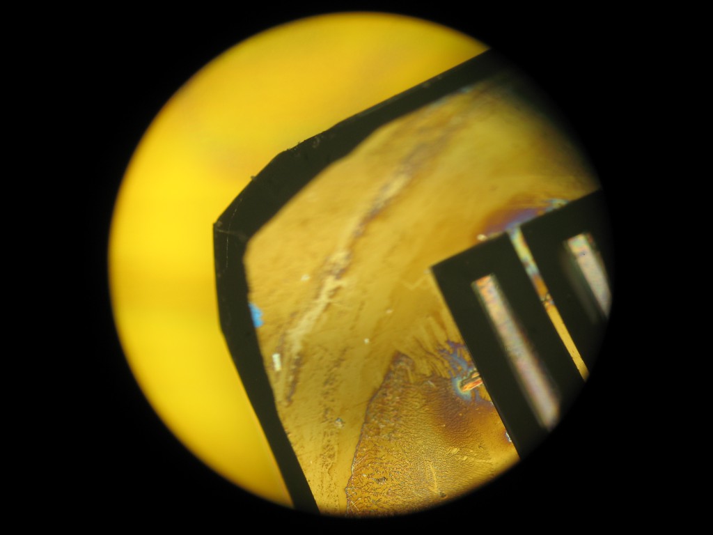
After monitoring the current flowing into the gate, I noticed the membrane had some bubbles on it’s surface, so I hit the device off the table pretty hard to dislodge them, and ended up breaking the membrane. Oops. But when I pulled the chip out I was able to get some nice images of the chip:
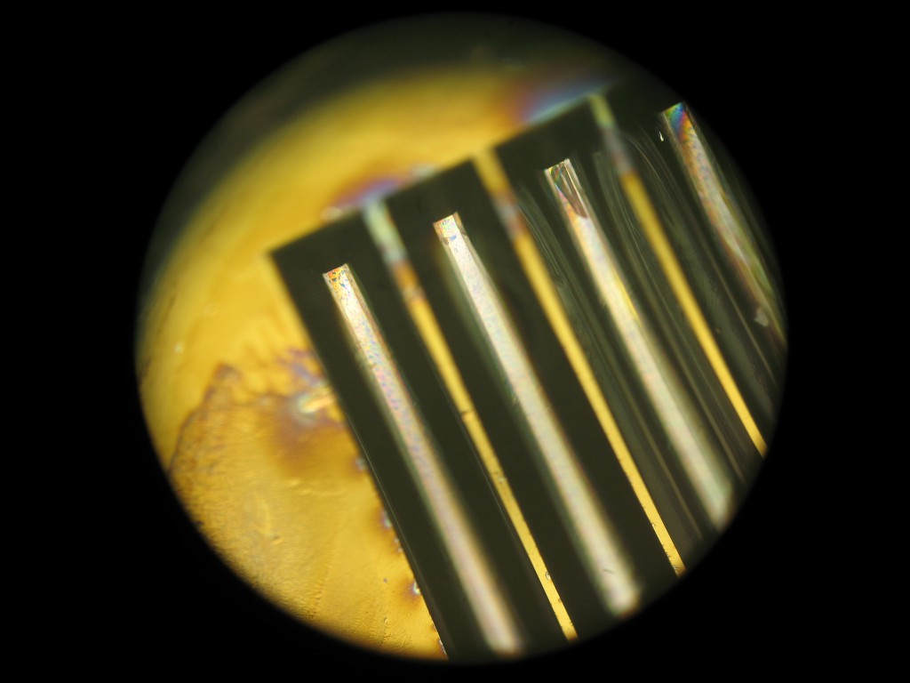
The chip wasn’t completely covered in silver, and one side had just 10 nm of Al2O3 covering a bare NPN substrate. You can see that transition in the above picture. The circular imprint is from the nitrile gasket. So there are four regions here – silver coated in Al2O3 inside the gasket, silver coated in Al2O3 outside the gasket, Al2O3 inside, and Al2O3 outside. Note that the simple Al2O3 coating didn’t seem to vary much from inside to outside, while the silver saw what looks like some substantial depositions on it’s surface inside and not at all outside. This is even more ovious in the next picture:

Speaking of depositions, I don’t think I’ve ever seen a freestanding membrane lift off and tie itself in a knot, as in the image below. I wonder if a layer of Ag/AgCl changed the strength properties in some way. 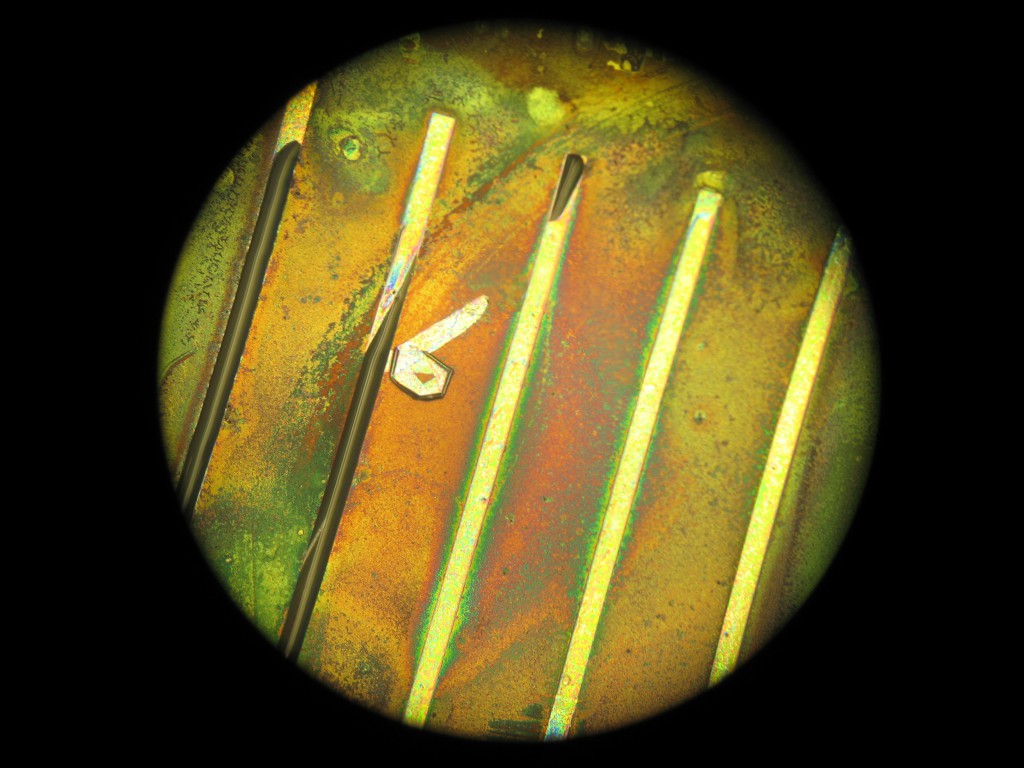
The backside had no silver, and as you might expect it saw no buildup of crud.
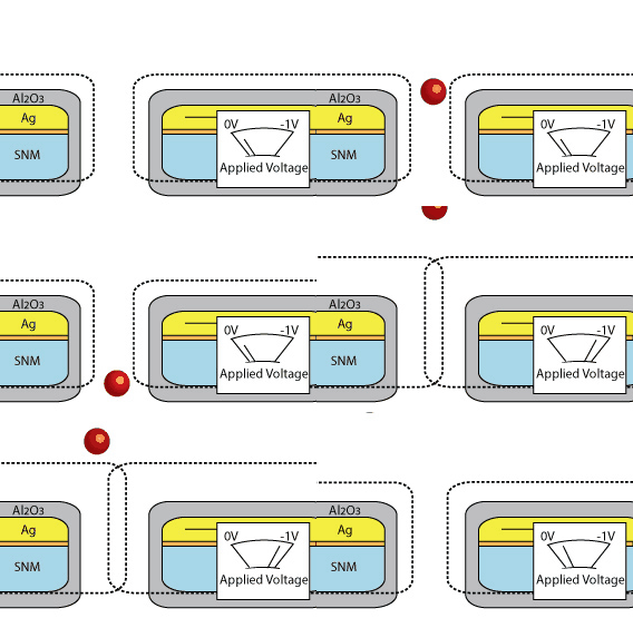
I’ve been using the term NanoFluidic Transistor (NFT) as a catch-all for any sort of electrically gated membrane, and especially used it to refer to charged membranes that can stop or allow the translocation of gold/DNA/drug molecules. But as Jim pointed out, the better term for the DNA/drug delivery device is ‘voltage-gated silicon nanomembrane’, since we aren’t interested in the modification of the current across the pore as much as we are interested in the sieving behavior of larger charge-carrying molecules (the red dot of gold/DNA/drug in this gif). But for EO, since the flow is dictated by the current (i.e. the flow of ions), and our charged gate directly modifies this current, I think we are safe in referring to the device as an NFT.