A First Attempt to Generate Ultrasound with pnc-Si EO Pumps (with Stephen McAleavey) was Inconclusive.
After seeing my previous post on modulating EO pumping behavior with an applied voltage, Jim asked if we could use pnc-Si as an Ultrasound generator. In the following video, I gave it a shot:
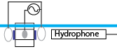
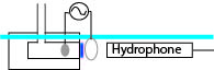
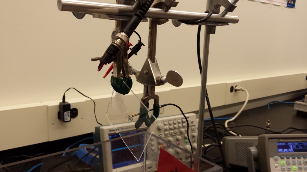
(relevant points from the video: a square wave of +/- 10V applied across a pnc-Si membrane results in apparently instantaneous response of the meniscus head in the capillary leading away from the setup. This response becomes invisible to my microscope-enhanced eye at 30 Hz, which is the frame rate of standard TV. I take the frequency of the signal up to MHz, and then back down to demonstrate that the membrane doesn’t tear itself apart). The setup this was taken with looks like this:
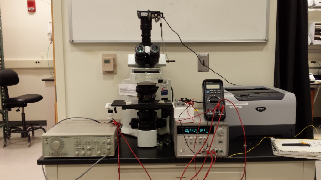
The problem, of course, is that we have no way of detecting whether ultrasound is being generated. So I got in touch with Professor Steve McAleavey to see if he had an ultrasound hydrophone we could use. Apparently there is a demand for robust micro-ultrasound generators, with the lower bound of usefulness being somewhere around 1 MHz. After showing him the setup in the video, we discussed the best way to measure ultrasound, and I ended up ginning up a little device:
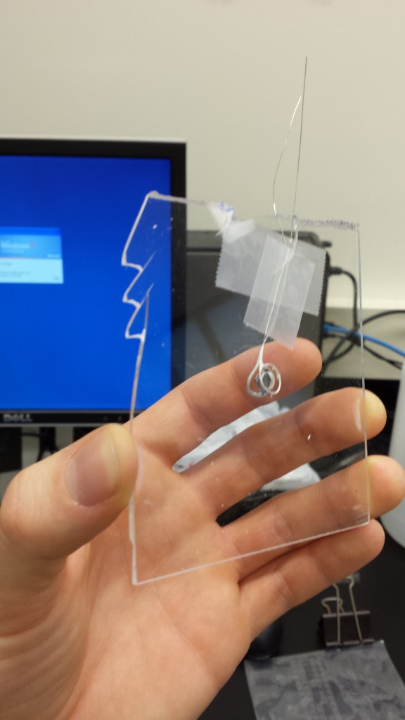
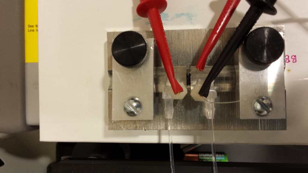
This picture shows a ~ 10cm x 10cm square sheet of acrylic plastic with a small hole drilled through the center. A pnc-Si membrane is affixed to the hole with one of our standard square silicone gaskets. Two silver wires are twisted into loops circling the membrane (but not directly in front of the membrane so as not to interfere with the wave propagation). These loops were dipped into Ag/AgCl ink and affixed with scotch tape.
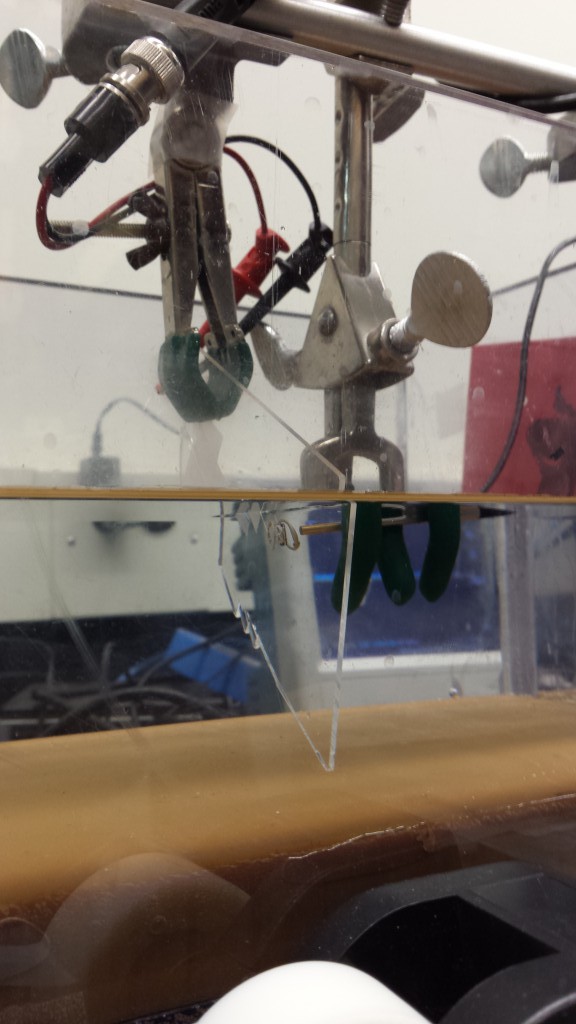
I took the whole setup to Professor McAleavey’s lab, and there we immersed the ultrasound device into a 10 mM KCl (unbuffered, pH was not measured) bath. We used a syphon to get the fluid into the bath, since pouring can introduce bubbles into the system that can do terrible things, like scatter ultrasound or even cause pitting of the hydrophone. An ultrasonic hydrophone was attached to an oscilloscope and fixed in place ~2-3 cm away from the surface of the membrane. We verified the hydrophone was working with a 3.5 MHz ultrasonic transducer, and then attached the leads of the Ag/AgCl electrodes to the function generator that applied +/- 10V in either a square or a sine wave at frequencies around 3MHz (we varied this somewhat).
We saw nothing.
We repeated the experiment with a new chip, and also saw nothing.
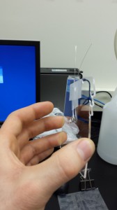
Interestingly, the Ag/AgCl electrodes seem to decay faster when a square wave was applied to them, as opposed to a sine wave. Also, the two electrodes decayed in very different ways, as represented in the picture below:
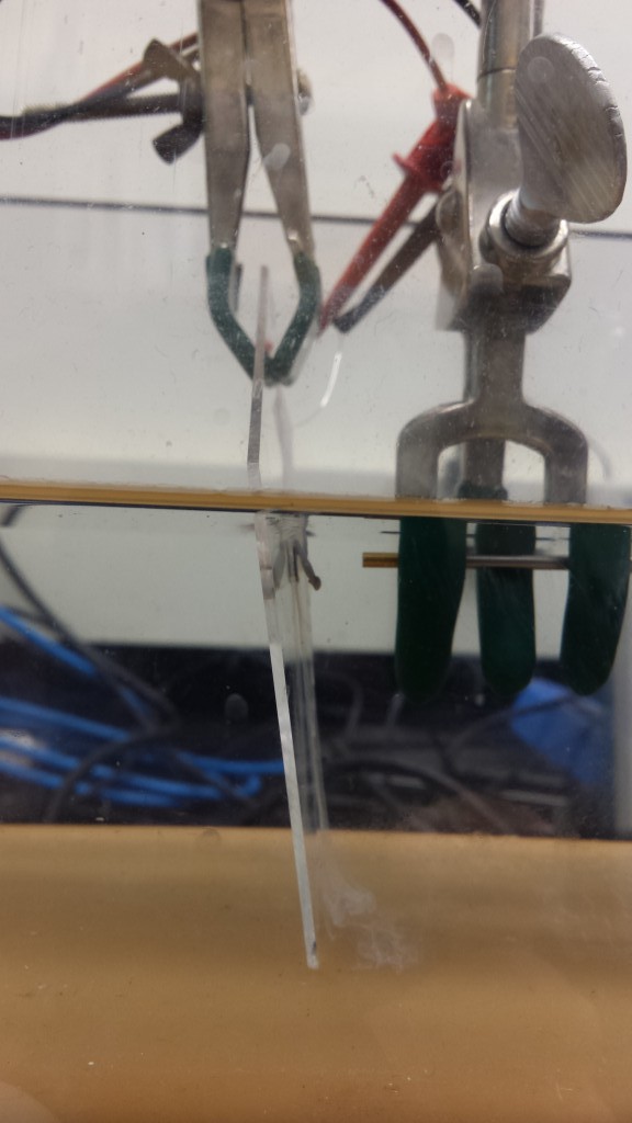
The electrode on the far side of the sheet (from the hydrophone) released gas bubbles, while the one on the near side simply shed it’s silver.
Discussing the failed experiment, Professor McAleavey hypothesized that what is happening is that even though fluid is moving through the pores, the membrane is flexing in the opposite direction, so that the net result is that no wave is propagating. Apparently that problem has beset numerous other attempts to build micro-ultrasound generators. After thinking about it for a few days, though, I’m unconvinced that we were getting any voltage across the chip. Note that the hydrophone we used was insensitive to sounds below the MHz range, so we were not able to verify that the chip was working in the range that I had seen in the microscope setup. We went with the acrylic sheet design because we were worried that if the back end of the chip weren’t open to a large bath we could get large back pressures or other weirdness. We assumed that the sheet was large enough (and the resistance of the fluid was large enough) that all of the voltage would go through the hole, and through the chip, driving EO. So I filled a beaker with 10 mM KCl and measured the electrode to electrode resistance in two states – hole opened (no chip affixed) and hole closed (a glass coverslip was taped over the hole, and I inserted the setup in such a way that there was a bubble in the hole).
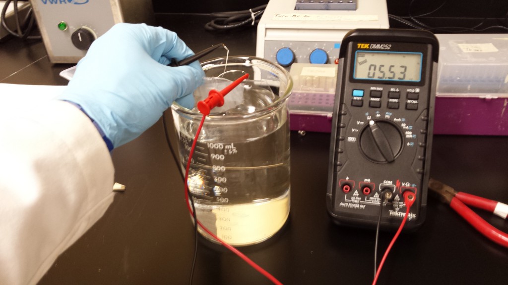
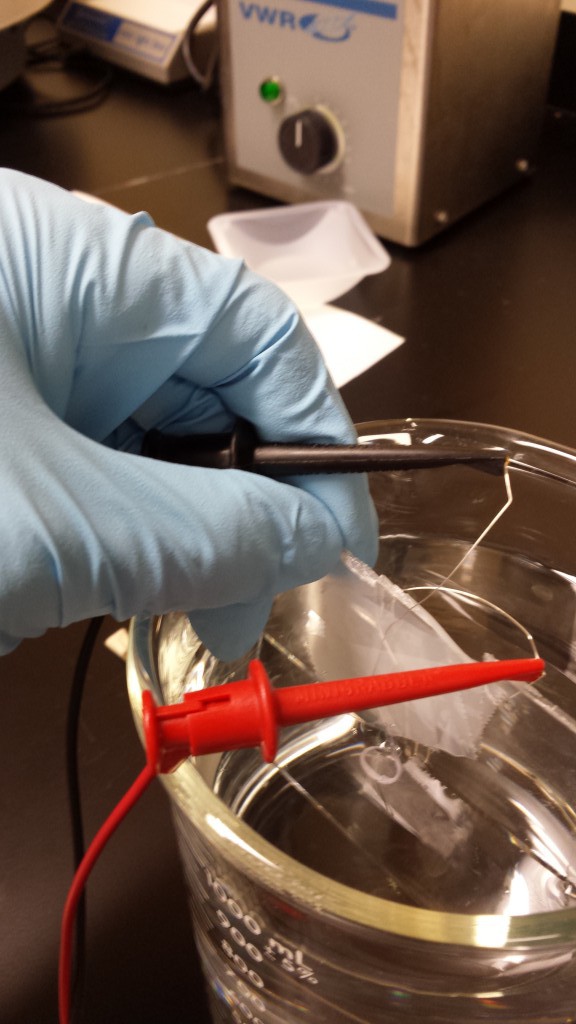
I was unable to see a significant difference in resistance between the two states. I think all of the voltage was escaping around the acrylic sheet.
I think it’s worth taking another crack at measuring ultrasound with a better setup, and once I’ve made such a setup I’ll be back in touch with Professor McAleavey.