Zetapotential Progress
I’ve been going to considerable lengths to try and get reproducible zetapotential measurements from my streaming potential device. Zetapotential measurements are the closest we can experimentally get to measuring the surface charge of a membrane, and are important for three reasons. First, I need accurate surface charge data for the membranes if my electrostatic model is to be accurate. Second, we’ll be able to find the pH of the isoelectric point for bare SiN and alumina-coated SiN chips, allowing us to make membranes with essentially no charge (which has been a goal of the group for several years now). Finally, verifying that changing the applied voltage to a nanofluidic transistor changes the zetapotential is a necessary proof of the nanofluidic transistor prototype I’ve made. The measurements are important, I’ll be making lots and lots of them for my thesis, and any gains we can get in chip-to-chip reproducibility, stability across multiple measurements on the same chip, or ease of measurement will make my life significantly easier in the future.
That said, this kind of electrochemistry is fickle. Although the system has only three components (the membrane, the salt solution, and the electrodes) they interact in complex ways. In this previous blog post, I described my device. In this blog post I described my earlier, successful efforts at eeking out a series of remarkably precise zetapotential measurements of both pnc-Si and SiN (both 5 slot format chips). For those measurements, I used silver wires coated in a commercial Ag/AgCl ink. The measurements were quite noisy before ultimately stabilizing, a behavior I attribute in hindsight to the fact that all the ugly measurements were in fact seasoning the electrodes. I ended up using the same pair of electrodes for EO, which ruins them, so when I returned to streaming potential measurements it was with new electrodes. At this point, we began to run low on 5-slot SiN chips, and there were more pressing uses for them in the lab, so I decided to switch over to using 3-slot SiN chips.
I’ve reached several conclusions, the most important of which is that the protocol I developed for the data detailed in the last blog post is in fact the optimal one. I’ve done experiments now with different salt concentrations (10 mM and 100 mM), different ways of preparing the salt (filtering the salt through a 0.2 um filter), three different ways of making ag/agcl electrodes (ink, electroplating, and bleaching), and two different ways of seasoning electrodes (passing an AC current through the electrodes or letting them sit while grounded to each other, and both conditions were performed in both high and low salt). I’ve used two different voltmeters to measure voltage drop. And I have played with the parameters involved in actually taking timepoints. All of these changes resulted in datasets that had larger standard error.
Takeaways:
I made two batches of coiled Bleach and electroplated electrodes, both of which had dc-biases that fluctuated so rapidly and were so sensitive to the flow of salt that they were useless.
Bleach and electroplated electrodes that consisted of just a bare wire (not twisted in a coil) required long wait times for the dc-bias to settle (~40 minutes) before a measurement could be taken.
Bleach electrodes had higher standard deviations in zeta measurements than ink electrodes. They also seemed to have only a short useful life span (~8 measurements) before their potential drift rendered them useless.
Soaking any electrode in a higher salt concentration than the one you’re using results in fluctuating potentials. Soaking in a beaker filled with the salt you’re using for measurement seems to work better than soaking them in the chamber.
Cleaning bleach electrodes with ethanol and DI doesn’t restore their potency.
3-slot chips have significantly higher flow rates at pressures of interest and are less well-behaved than their 5-slot counterparts.
cleaning chips with a 100W oxygen plasma for 2 minutes doesn’t seem to dramatically change their surface potential. It may diminish chip-to-chip variation, but N = 2 so I can’t say for sure.
There are still some standing questions, the most pressing of which is how to season new ink-coated ag/agcl electrodes so they perform at the optimal level. I’m disappointed that none of the variables I changed improved my data collection, but it was important that I try them, and it was especially important that I confirm that bleach electrodes and electro-plated electrodes perform similar to ink-coated ones but with more noise.
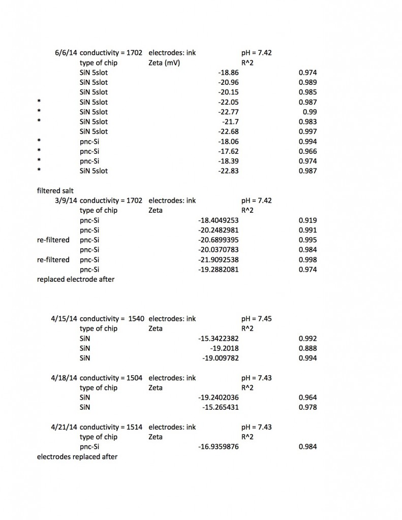
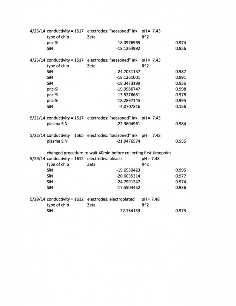
This excel spreadsheet (Zeta results up to 6:5:14 summarized) contains my raw data, including some extra goodies I’m not showing below, such as how DC offsets at zero pressure change after a measurement. I’ve been able to read zetapotentials from 41 individual chips (the chips were a mixture of 5-slot pnc-Si and 5 and 3-slot SiN) and I usually collected the zetapotential three times on each chip.When I was using bleach electrodes it was necessary to wait for forty minutes for the system to stabilize, but thankfully the protocol I’ve chosen requires only about ten minutes for a single zetapotential measurement.
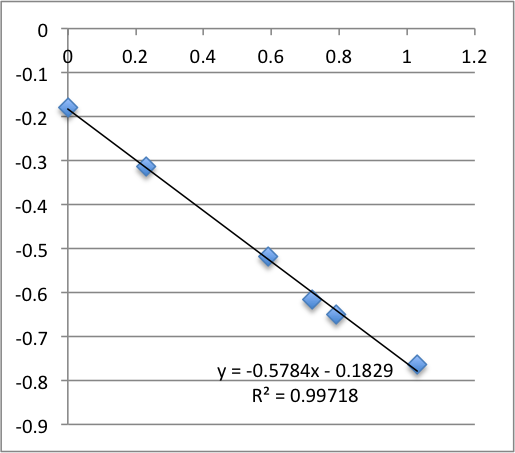
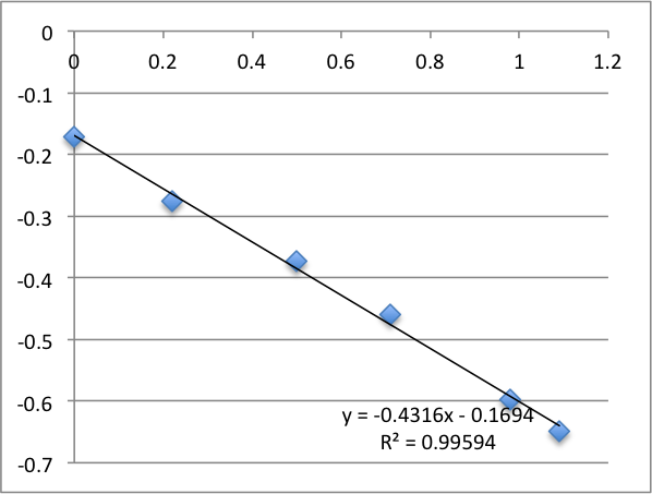
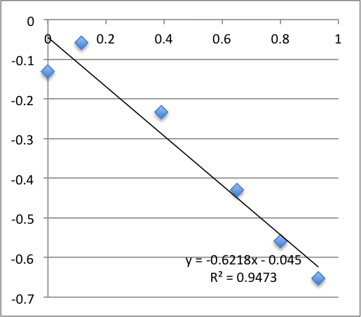
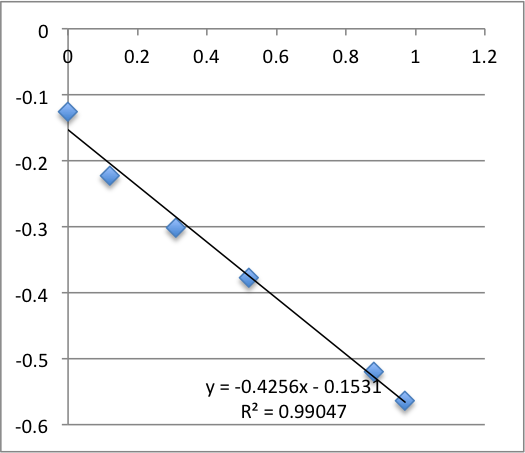
The following data is pulled from graphs that look like this:
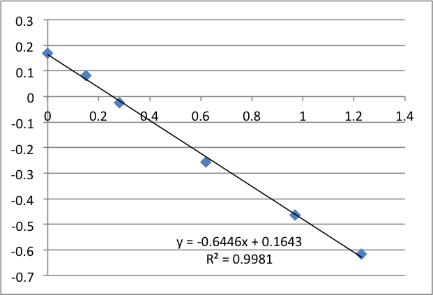
X-Axis is pressure in PSI, Y axis is mV. The slope is used, via the helmholtz-smolachowski equation, to get the zetapotential. R^2 is reported as it’s shown on the chart.
I found SiN 5 slots had a zetapotential of -21.5 mV +/- 1.4mV. In my best data set pnc-Si had a zetapotential of -18.0 +/- 0.4. Repeating the pnc-Si with the ‘good’ electrodes but a new buffer pnc-Si had a zetapotential of 20.1 +/- 1.2 mV, and if I include every measurement with an R^2 > .9 I get
SiN 5slots: -21.5 +/- 1.4 mV
SiN 3slots: -19.5 +/- 3.0 mV
pnc-Si: -18.7 +/- 2.0 mV
These numbers include new electrodes and a variety of experimental conditions, so the standard deviation should come down when I go back to my standard protocol, but the data suggests that distinguishing between the zetapotential of pnc-Si and SiN will be difficult.
To this end, I ran three more experiments yesterday (6/9/14). All three were performed with 3-slot SiN chips using a new pair of ink-coated electrodes that had been allowed to equilibrate in a beaker of the test solution all weekend (~70 hr). The conductivity of the system was 1565 uS/cm and the pH was 7.43.
First Chip. All charts are pressure (x-axis, psi) vs. streaming potential (y -axis, mV).
I took two measurements on each chip. First chip first measurement gave a zetapotential of -18.5 mV, the second -13.8 mV.
Second chip first measurement was -19.9 mV, second measurement was -13.6 mV.
Third chip was -17.9 mV. It broke during the second measurement.

Statistics for this run: Average zetapotential -18.8 +/- 1.0 mV.
There’s some weirdness in that the systems seems to grow more chaotic with successive measurements, but my hunch is just that the electrodes are still being broken in. I’m prepared to call this good enough.
Notes for anyone duplicating these results:

0.1253 g phosphate (dibasic) and 0.0381 g phosphate (monobasic) and 0.7455 g KCl in 100 mL diluted 10 to 1 gives 1 mM phosphate buffer 10 mM KCl at pH 7.4 and conductivity ~1550 uS/cm. Filtering this through a 0.2 pall aerodisc filter appears to have no positive effect on zeta measurements.
The more general formula for making weakly buffered (10 mM) phosphate solutions at different pH’s is as follows.
Use the first chart on this page for the ratio of monobasic to dibasic for the desired pH. Note that the MW of monobasic potassium phosphate is 136.09 g/mol, and dibasic is 174.18 g/mol. For a pH 8 solution, 94% of the added phosphate should be dibasic (K2HPO4) and 6% monobasic (KH2PO4). Since we want a 1 mM solution, we would add .001 * .94 * 174.18 = 0.1637 g dibasic and .001 * .06 * 136.09 = 0.0082 g monobasic to 1 Liter H2O. KCl has a MW of 74.55 g/mol, so we add 0.7455 g for 10 mM KCl. Since 1 liter is an impractically large amount, we add the same amounts to 100 mL and then dilute 10x.
For pH 5.8, we want 8.5% dibasic and 91.5% monobasic. So we would add 0.0148 g dibasic, 0.1245 g monobasic, and 0.7455 g KCl to 100 mL, then take 10 mL of that stock and add 90 mL of DI water to it.
Hi Karl, great work! It’s interesting to hear you have unstable behaviour with the electroplated/bleached electrodes under flow. One way to avoid these artifacts in general is to use a salt bridge between your electrode and the bulk solution. For patch clamping i usually make an “agar bridge” using a 3% agar or agarose solution in the chosen bathing medium. This can be gently melted together (don’t boil) before drawing up into a glass capillary or similar. The Ag/AgCl wire electrode is then fitted into the resulting gel at one end and the other end immersed in the liquid. This has two benefits – one is the removal of flow artifact by clamping the local conditions at the electrode interface, the second is that when passing current it avoids any free Ag+ ions from entering the recording chamber. There may be reasons why this is impractical/inconvenient but may be worth a try? Agar is not a magic ingredient – essentially any gellation agent would work if you have another preference.