Over the past year, our lab has been working in close collaboration with the Schwarz lab to design, develop, and manufacture microfluidic transwells for their P50 project. The project was initiated after the discovery of S. aureus migration through sub-micron canaliculi in vivo. To further explore the genes involved in this newly proposed mechanism of immune system evasion, the Schwarz group collaborated with our lab to hand build transwell devices that would allow them to mimic the confined geometries of the canaliculi. After the initial experiments involving strictly wt staph, candidate mutants were developed and are now in the process of being tested. In order to facilitate faster biological experiments, we contracted out Aline Inc, a microfluidic company based out of southern California, to build these transwell devices in large batches.
Design Stages
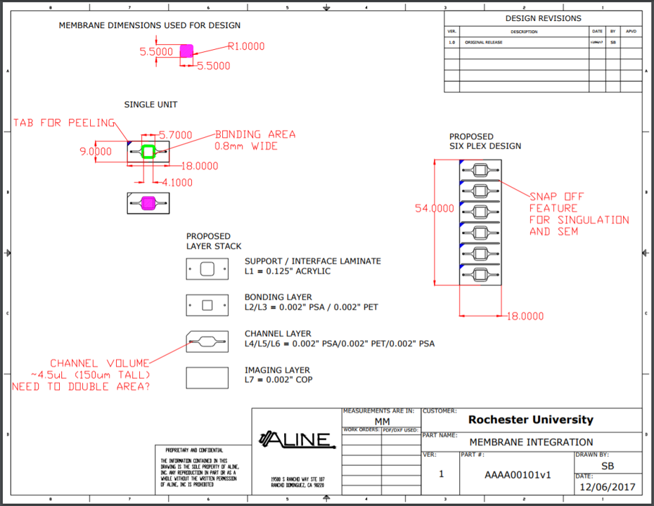
Figure 1. First formal Aline design. Bonding area was suited for three slot 0.5 um SiO2 format chips. The six-plex design was implemented to facilitate multiplexed experiments in an easy to handle format.Figure 2. Membrane failure during production highlighted a potential problem with the high number multiplexed design: if one membrane fails, the whole ‘device’ is not suitable for delivery. It was also harder to handle the six-plex devices then expected at this stage. For these reasons the design was changed to fit a three-plex need.Figure 3. High fluid resistance through the bottom channel, coupled with tiny access ports, made it near impossible to load the bottom channel of these devices. The bottom channel and access ports were both increased in size to adjust for these issues.
Figure 4. The discovery of potential leaks in the system lead to the shrinking of the sealing layer. This final design was easier to load through the bottom channel and was leak tested to confirm nice bonding.Figure 5. Leak testing confirmed firm bonding of the sealing layer to the Si chip.
Membrane Design
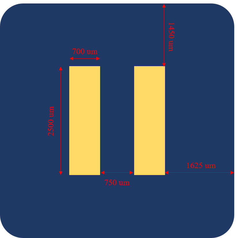
Due to concerns over the available three slot bonding area, two slot chips were designed. This design maintains high membrane area, while increasing bonding area.
Figure 6. 2-slot membrane format.Figure 7. Since completion of the design, we have been able to integrate a variety of membrane formats. The yields from these builds will help guide our future production runs.
After seeing my previous post on modulating EO pumping behavior with an applied voltage, Jim asked if we could use pnc-Si as an Ultrasound generator. In the following video, I gave it a shot: MVI_2604 (relevant points from the video: a square wave of +/- 10V applied across a pnc-Si membrane results in apparently instantaneous…
We’ve known for some time that the sieving coefficient of our membranes changes over time. The reason for this is that at the start of the separation the concentration just above the membrane is the same as the bulk concentration, but as more and more fluid begins to pass through the membrane we get concentration polarization, and the membrane…
In my continuing efforts (previous post) to create a nanofluidic transistor, I recently repeated some of my earlier attempts to prototype a basic Si-Ag-Al2O3 stack. This time, however, I used SiN chips from wafer #1070 (<40 nm>). As before, I aimed for a ~3 nm Ti adhesion layer (4.3 nm actually) and a 12 nm…
I’ve been working with the Corning transwell inserts and our SepCon units a bit recently. The addition of the Dremel last week has allowed better control while cutting the transwells, even without the right angle attachment (which will allow cutting in the “drill press” mode). I attached a picture of the process and final unit….