Electrophoretic Cell
Because of Harold Smith’s project, Rachel and I have been working on various methods to get proteins through a pnc-Si membrane and onto a polymer membrane. The particular system that Dr. Smith wants to study is very sensitive to ambient RNAses, molecules that digest RNA. This means that the long times required for a diffusion experiment are probably not possible in this system. The other options we have considered are pressure and electrophoresis to pull the proteins through the pnc-Si membrane, and with our current membrane stock pressure is unreasonable.
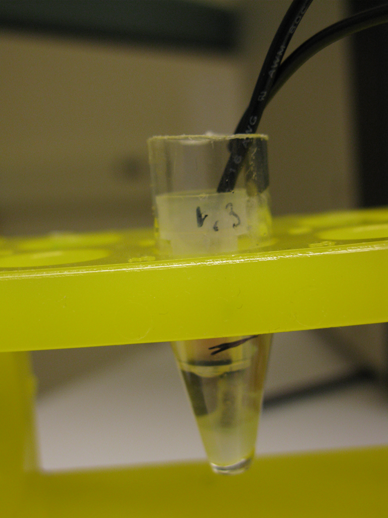
Rachel and I constructed two simple electrophoretic cells together, and achieved a cell that works after some trial and error. All of the following experiments are performed using pinhole membranes from w621. Our first mistake was using wire that corroded in the salt solutions we used, but our final design uses platinum wire. Initally we made a vertically aligned cell using the SepCon in a slightly modified EQ format. Wires were inserted in the SepCon bucket and the reservoir under the bucket. We noticed that once we turned on the power, the hydrogen and oxygen gas generated from electrolysis at the wire created an air bubble that rested directly below the membrane cutting off any hope for electrophoretic transfer through the membrane.
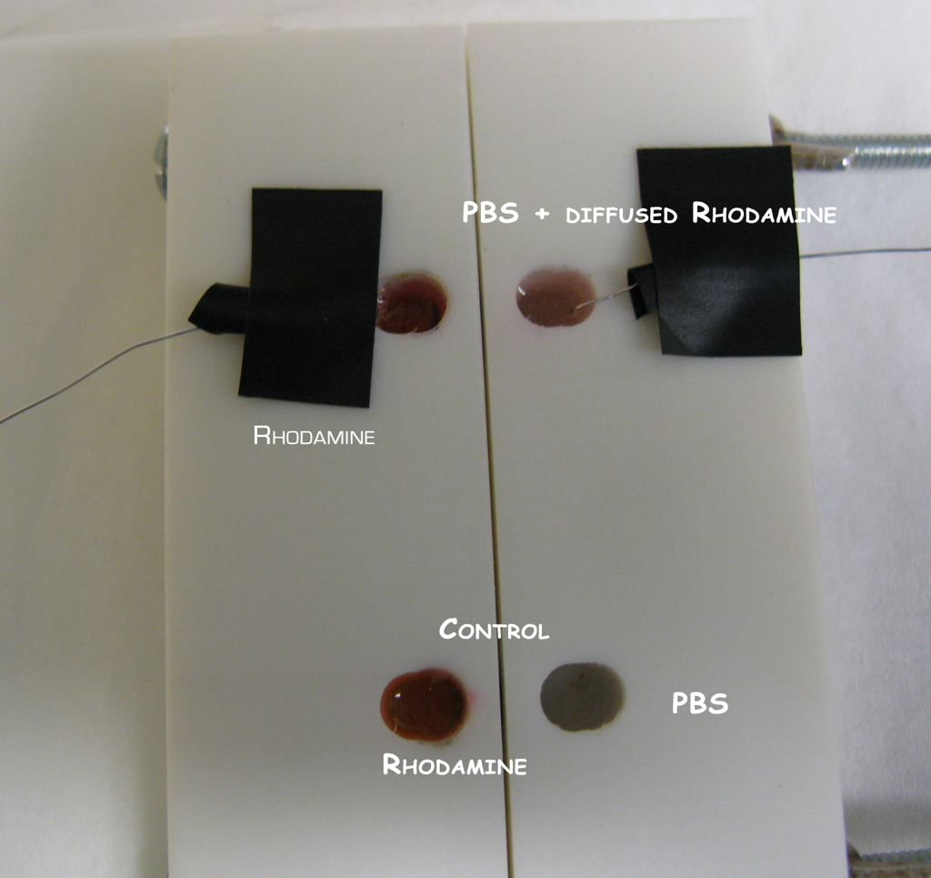
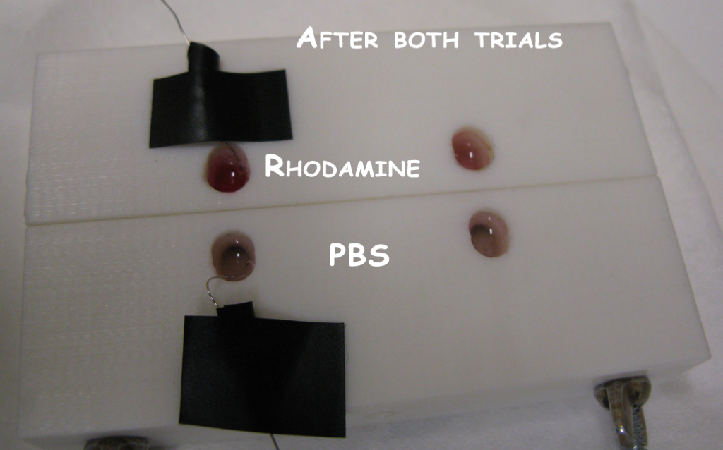
We moved on to using the horizontally aligned stir cell for our next tests. We selected two membranes with pinholes and inserted them into the stir cell. The stir cell has the capacity for two trials, and we filled one well with .5mM rhodamine (in PBS) and one with PBS for both trials. Both were filled at the start of the experiment. The idea was that we would test one of the membranes and let the other rest during this period to see if passive diffusion through pinholes matched any outflux of rhodamine during electrophoresis. We assembled the first trial with a negative Pt wire in the PBS well and a positive Pt wire in the rhodamine well. We turned on the power supply to 30V (the current was about 14mA). Immediately bubbles formed at the wires indicating that electrophoresis was taking place. Within a minute the PBS well of this trial was beginning to turn pink, while the control well was still clear. After 5min the PBS well had turned pretty significantly red (note we haven’t quantified any kinetics or concentrations yet for this first attempt), so we disconnected the power and connected it up to our control well. We repeated the same results with this second well.
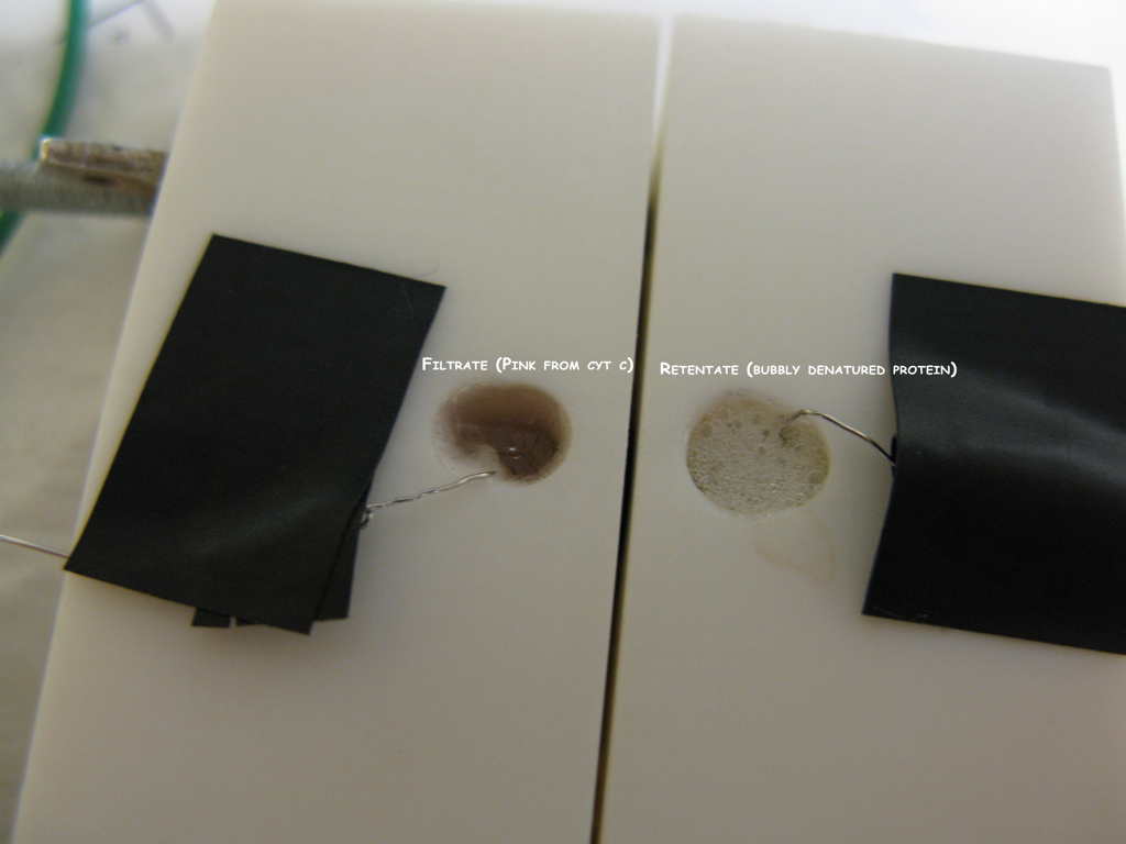
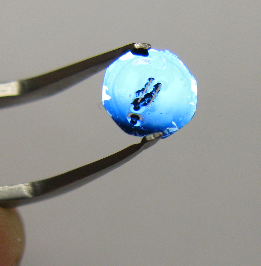
Finally we moved on to a protein system. 2mg/mL cytochrome c was placed in one well and PBS in the other. Cytochrome c has an isoelectric point around pH9-10, so in this neutral system it should be positively charged. We placed the negative wire in the PBS well and turned on the power. While noticably slower than rhodamine, cytochrome c began to move into the PBS well. The problem with the protein solutions is that the bubbling from the wires causes the solution to foam since proteins were probably denaturing at the water air interface. We also noticed a scum like substance on the membrane after the experiment, which we think could have been a mass of denatured protein. It’s possible that there is some denaturing from heating during the experiment too. Release of hydrogen during electrolysis might make the solution pretty acidic too, right? One thing I’ll mention is that after we had finished the electrophoresis experiment, I tried switching the electrodes and I think (but can’t back up) the solution may have gotten clearer as cytochrome c moved back to the first well.
At any rate, it was nice to see these rough experiments work out for us. We’ll try some more tests, including isoelectric focusing with different pHs, quantification of the kinetics, and actual separations with intact membranes. We also need to make sure that the electrophoresis is not breaking the membranes and giving us false positives.
Awesome!
Chris pointed out that one obvious explanation of the sludge is just a “cake” – if you really did send almost all of the protein across our pores within seconds-minutes, then that’s an incredible protein flux through our pores. I would definitely expect a build-up of protein at the retentate side of the filter. At 2mg/ml of CytoC in ~300 uL – you’re almost talking about a whole 1mg, which if pushed up against the wall of our membrane would look like a glob (technical term). Maybe it’s denatured because of a high electric field at the membrane, but maybe not – I’d expect a glob either way.
Please confirm that the glob formed on only one side and that it was the protein source side..
Yes, these results are very interesting, and until the membranes get stronger, it’s certainly a good way to get species to move across the membranes. One thing that I would suggest doing is taking 2 platinum probes with a multimeter to see what the voltage drop is between the 2 chambers. I would also move them around a bit to see if the voltage changes. It seems like the voltage would drop mostly at the electrodes and at the membrane, with little voltage drop in the solution, but it needs to be measured to confirm. If most of the drop is at the membrane, stirring would help a lot. It may also reduces the cake formation.
Great work, and thank you for using platinum, like the rest of the world!! This will also help us with the NSF project.
Any reason why you chose 30 V? I’m not familiar with this kind of stuff… did you use a procedure from literature?
Right cake formation makes sense here. I’m not sure if this was formed on the retentate side though. When I pulled it apart I wasn’t expecting to see this, but next time I set one up I’ll be sure to check.
I’m not sure if we have a multimeter or not. Do you guys have one handy?
And 30V was just what the power supply happened to be set at. I had no real idea what to choose. I only know that electrophoresis in gels is run more around 180V, which is higher because of the huge resistance in the gel.
There should be a multimeter under the workbench in one of the drawers.
If that deposit is cake, it should be on the retentate side only. Lowering the voltage would probably be a good idea – I would suggest 5-10V. This situation is somewhat different than a gel. In a gel, you are setting up a constant voltage drop over a fairly large distance. In these experiments, it’s difficult to figure out where the voltage drops. I assume there is a significant drop across the membrane itself, but I have no idea what fraction of the voltage this is, though. Interesting…