Ultrasound Generation via NPN Still Doesn’t Work, Even in Low Salt
Two years ago (blog post), I asked Professor McAleavey to help me see if we could use NPN chips to generate ultrasound. I’d found a paper (An exact solution of AC electro-kinetic-driven flow in a circular micro-channel) that suggested, given the geometry of our chips, that if the chips could be used to generate sound, they’d be responsive up to the gigahertz range, which would make them clinically useful. We played around with a setup for a few days but were never able to see an ultrasound signal.
I don’t know much about ultrasound, but Professor McAleavey thinks that there’s substantial room for improvement over the existing piezoelectric ultrasonic generators. Also, poking around, I found this paragraph:
If they want to integrate huge arrays of these microphones and transmitters, wouldn’t it be great if the microphone and speaker could be made using the MEMS toolkit?
With the success last week of my ACEO vortexer, I learned that certain electrokinetic phenomena only work in low salt concentrations. In particular, the vortexes I generated only happen in solutions below about 10mM KCl (although figuring out this upper bound is an active area of research). The experiments from two years back were performed in 10mM KCl, so it seemed reasonable that repeating them in Barnstead water might give us ultrasound.
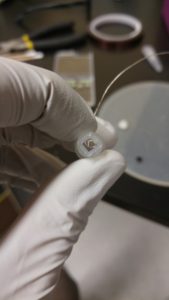
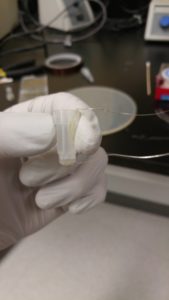
The first thing I did was modify a lapel microphone that I had purchased for my podcasting efforts. I placed the lapel in a condom to make it waterproof, and effectively made it into a hydrophone. The lapel microphone actually records in stereo, weirdly, meaning it has two channels – a left and a right – that are recorded independently. That’ll be important later. Audio was recorded using a handheld H4N field recorder.
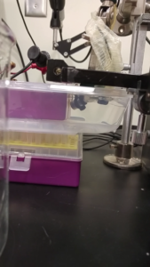
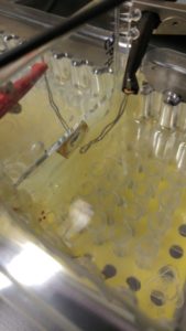
Next, I taped an NPN chip (from wafer 1142 – pore diameter ~35 nm, porosity 8-17%) to a tip box with a hole drilled into it. Then I used the two micromanipulators to position two platinum wires on either side of the chip. I used an oscilloscope to generate audible frequencies (400-9000 Hz) and used an online tone generator to check to see what I should expect.
The hydrophone was definitely getting the signal I was inputting, and I thought this was a clear demonstration of my success. But then, I put the wires both on the same side of the chip, so they were separated by nothing but water, and the hydrophone also picked up the signal I was putting out.
The problem, I quickly discovered, is that the hydrophone can pick up the electric field (it’s basically a magnet suspended in a coil attached to a diaphragm, so strong fields can cause the magnet to move regardless of whether the diaphragm is vibrating). And to the microphone, there is no difference in the signal due to pressure changes and the signal due to field strength.
I tried a couple of different ways to “sanitize” my signal – i.e. remove the electric component so the hydrophone only picks up the audio component. The thing to recognize about the two components is that they have the same frequency, but the audio component should be phase shifted. What I mean is that the electrical component propagates through the water at the speed of light (2.5 x 10^8 m/s), while the hydrophonic component propagates through the water at the speed of sound through water (1.4 x 10^3 m/s). What I thought I could do is take the two channels of the lapel microphone, invert them, and add them together. I though that the electric component of the signal would perfectly cancel, but that the water component, being slightly different across the surface of the microphone, wouldn’t.
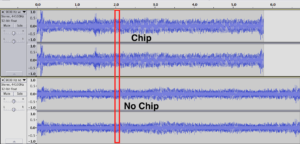
Raw audio from the hydrophone (I ported it into Audacity, a free audio editing software that’s pretty powerful under the hood but that looks straight out of the nineties):
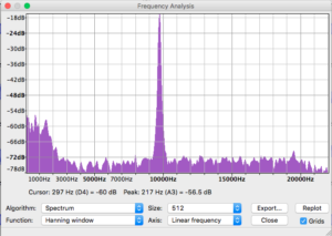
Spectral Analysis of the red region:
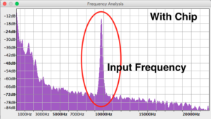

There are well defined peaks in the Fourier transformation plot at 9000 Hz, which was my input frequency (I chose 9,000 because it’s reasonably high energy, but it didn’t hurt my ears the way 16,000 or 12,000 did). The peak looks more or less identical in both cases.
Here’s a close up of the red region (10 ms) for the “with chip” case:
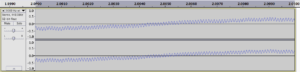
The tight knit “stitches” are the 9000 Hz signal, which seem to be riding on some lower frequency noise (which we expect from looking at the Fourier transformation plots). I inverted the right channel:
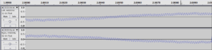
And merged the two tracks:
![]()

This would seem like pretty good evidence that we’re getting a hydrophonic component on top of the induced current signal, except that the analysis for the no-chip case looks very similar:
![]()
There’s a lot to chew on there, but it does mean that there’s not going to be an easy way to measure audio in such strong electric fields.
At this point, I spoke to Professor McAleavey again. He was on his way out the door, so it wasn’t a long chat, but his first suggestion was “Why don’t you try adding more power?” He pointed me towards Paul Osborne in ECE and recommended that I ask for an audio amplifier. I wasn’t sure exactly what more power would do, but I figured it would do something. Maybe I’d be able to hear it with my ears (which are much less susceptible to electrical stimulation). Maybe it would shatter the membrane.
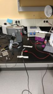
Paul Osborne didn’t have an audio amplifier, but it turns out I had one in my basement, in the form of a guitar amplifier. This was my new setup:


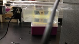

I hooked up my computer (which is using the online tone generator to make a noise) through the headphone jack into the 1/4″ guitar amp input. From there, the amplifier has a “Output to speaker” jack. My roommate had a busted 1/4″ cable that allowed access to the wires on one end of the cable, and so I hooked up the oscilloscope inputs to the guitar amp. The oscilloscope recognized the tone I was generating. I easily topped out the oscilloscope, which can only measure peak-to-peak voltages of 40V before clipping the signal. So I’d estimate I was applying 60-100V across the two platinum electrodes. And I saw nothing.
EDIT: I used a voltmeter to measure the peak-to-peak voltage outputted from the guitar amp. It never gets more powerful than 20 V.
The hydrophone picked up the field, of course. But that doesn’t mean anything, we learned before.
I next tried applying a DC voltage of 20 V across the chip, to see if we got EO at all. The platinum wires didn’t bubble, meaning that there was no current being lost to the water. Next, I thought that maybe the solution wasn’t salty enough. I happened to have a syringe of 100mM KCl from some old experiments lying around, so I gave both reservoirs a squirt. Bubbles appeared on the platinum electrodes – presumably we were getting DC EO, although the reservoirs were so large it was impossible to tell if there really was pumping.
With the newly slightly salty water I tried my guitar amplifier setup again. And again I saw nothing.
I think the next step is to do some modeling in COMSOL, to try and get a sense of the expected field strength inside the nanopores. It could be that the gap between the wires needs to be an order of magnitude smaller before we expect to see an effect.
EDIT: I switched to using a chip from wafer 2226 with 10 nm of alumina on it’s surface. The alumina should make the SiN a better capacitor. I also moved the setup from the big gel-box container container to a single Sepcon, which forced the electrodes much closer to the surface of the membrane. I’d estimate that the two electrodes (which were I think steel wires, 160 um in diameter) were only 1 mm apart. The whole setup was held together with copious amounts of hot glue.
Using pretty much the same setup as above, I heard and saw nothing. I also made the water slightly salty, and saw nothing. Eventually I cranked the DC voltage way up and think I burned a hole in the membrane somehow – water began to leak out. I think I’m temporarily abandoning this project. My guess is we need prohibitively large voltages to see the effect, or the field effect means
Relevant Literature:
Capacitive micromachined ultrasonic transducers for medical imaging and therapy (fabrication of MEMS ultrasound generators. 25V operates their system).
Capacitive Micromachined Ultrasonic Transducers: Next-Generation Arrays for Acoustic Imaging?