Proof of Concept for a AC Electro-Osmotic Mixer on an NPN chip
I’ve been trying to make the following device work for the past few years: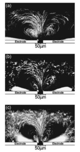

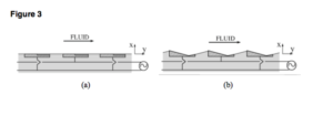
The people who have been studying this have been trying to use the phenomena to mix solutions, or using arrays of mismatched electrodes to generate a sort of conveyor belt pumping mechanism:
My idea is to use the electrokinetic phenomena of AC electro-osmosis to generate mixing vortexes to combat caking and fouling directly above the surface of an NPN membrane.
DC EO arises because when you apply a voltage across our membranes in low salt conditions, the pores are filled mostly with ions that have the same charge as the membrane, and they directionally migrate according to the field, dragging the water with them:
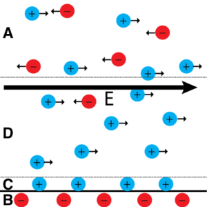
AC EO uses the same charged-wall-in-an-electric-field effect, but with a crucial difference:

(images from this helpful paper/review Bazant_2008_Ency_Microflu_Nanoflu_2)
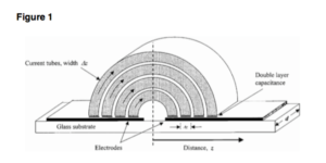
The field across the parallel plate capacitors sets up “current tubes”, which I think is just a confusing way to reference field lines. The smallest, innermost tube has the strongest field, and its ions condense to form the modified Poisson-Boltzman distribution that gives rise to the debye length. But the outer current tubes haven’t condensed and shielded the charge on their segment of the plate yet, so the inner tube region undergoes EO out towards the outer tube.
This is exciting because AC EO “breaks” the no-slip condition (technically it doesn’t violate it, but it should do a much better job of overcoming the negative effects of no-slip than mixers). No-slip means that there’s always a stagnant film above a membrane, and for us, because the boltzmann distribution that drives higher resolution is confined to the first hundred nanometers or less:
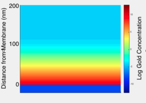
it means that stirring with a magnetic stir bar:
Doesn’t change the sieving behavior of the membrane (data not shown). So, I set out to replicate the paper first:
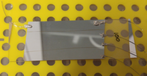
I made a series of glass cover slips coated in varying thicknesses of silver, with small gaps (either 160 um or 25 um), and then coated with 10 nm of Alumina.
Then I hooked them up to a function generator, put a sepcon gasket so it covered the gap, and loaded up the gasket with 7 uL of 1 um fluorescent latex beads.
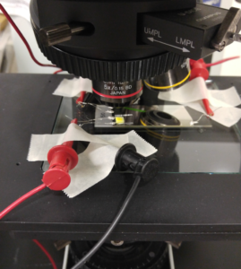
Notice that when I change the focal plane of the microscope, you can see the beads stop moving outwards and begin moving inwards. This is consistent with a vortex pattern as viewed from the top.
In the above video, I briefly put the system at very low frequencies. Two things happen – the beads rock back and forth (there’s no net migration away from the gap) and a pit forms in my dielectric.
The above video is the same thing as the previous two, just lit a little differently. 50 nm thick silver, 25 um gap, 100-1000 Hz, ~4V peak-to-peak, 10 nm ALD alumina over the whole thing. The conductivity (inverse of resistivity) of the solution with the beads was around 5 uS/cm (I made it by adding 500 uL of stock 1 micron particles to 30 mL of Barnstead water). For reference, Barnstead water is 0.6 uS/cm. The paper I took this from used solutions with conductivities of around 30 uS/cm. 100 mM KCl is 1440 uS/cm.
So then, I wanted to do the same thing to an NPN chip with interdigitated electrodes:

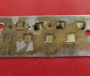
![]()
Remarkably, the silver thickness on these chips was just 12 nm. The mask also had the effect of making the gap larger than the 160 um wire I used as a mask, with a rough estimate of the final gap thickness at somewhere around 300 um.

(I think that the buildup around the shadowed mask represents the actual edge of the electrodes. The silver continues past the dotted buildup, but I think it’s no longer an unbroken film past that point.)
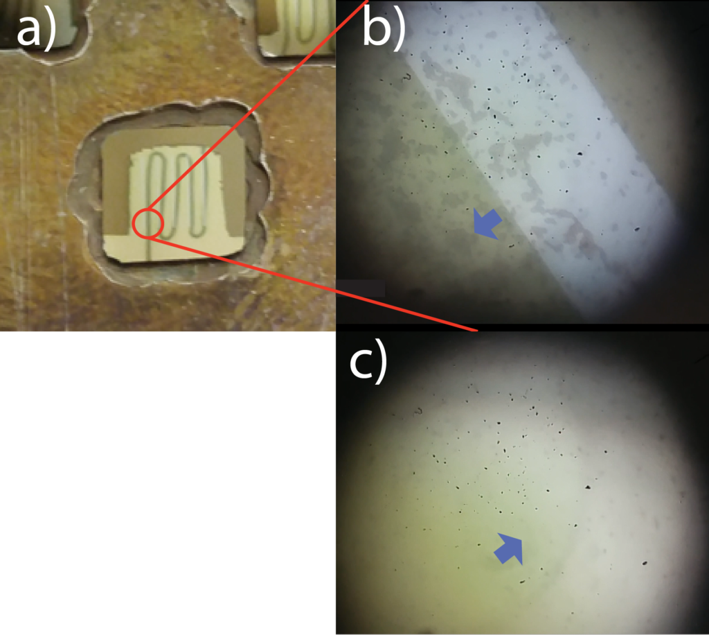
In the next two videos, ignore the big black dots that are super in focus. They were just schmutz on the microscope lens. I took these videos with my smartphone.
So this is a proof of concept of the AC-EO vortexer over a porous substrate. Next I need to image what happens when fluid is flowing through the membrane and the mixing is happening at the same time, and then we need to devise a few experiments to quantify what sort of improvement this device can give us.
A sad note – this device only works with low salts. I read somewhere the effect breaks down at around 10 mM, but I haven’t played around with it very much. The upper salt limit will be very important for telling us how useful this might be in the bio world.
Here’s another figure from the pdf referenced above:
