Slight redesign of liftoff dialysis device
In light of technical difficulties associated with the current liftoff device design, I’ve been working on a slight alteration to the design with an eye towards reducing leaking and improving the shape of the flow in the dialysate chamber.
The shape of the blood conduit has been demonstrated to be successful in distributing the flow fairly evenly amongst three channels separated by “fins” to support the freestanding membrane, so that remains unchanged.
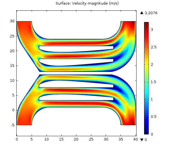
This design as shown contains two distinct conduits of symmetrical design, just to reduce the load on either one of them — this would be very important in high-velocity flows, where spreading evenly is particularly challenging. However, for our preliminary purposes (benchtop or heparinized small animal studies) only one conduit is necessary.
If it ain’t broke, don’t fix it. My resdesign of the dialysate chamber is in fact just the same shape as the blood chamber, but without the fins (as there’s no free-standing membrane to support — this means that when the device is dry it will need to be stored right side-up, but that shouldn’t be a problem for now.)
In order to test this design, I constructed the following silicone stack:

Elements 1, 2, 5, and 6 are 1 mm silicone while elements 3 and 4 are 300 um. Each layer is UV/Ozone bound to the adjacent layers. Layer 3 is intended to act as a placeholder “membrane” for prototyping, and will need to be replaced with an actual liftoff membrane in the future.
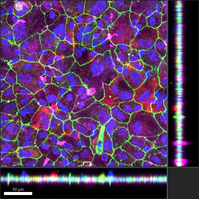
Once the bonding was complete, I penetrated the silicone at the inlets and outlets of stacks 2 and 5 with sharp 21g needles for access. I chose to flow colored solutions into both sides at 0.5 mL/min, since this is the flow rate of the peristaltic pump that we’ve been using for rat studies.
First, I filled the blood side with yellow dye solution (video) without any pre-wetting. Then I filled the dialysate side with blue dye solution (video). A distinctive green color is visible where the two solutions overlap in the stack, but no leakage between layers occurs, as evidenced by the pure blue color at the dialysate outlet. Note that for this device I forgot to mirror the dialysate channel so these flows actually went in the same direction — fixing this will be trivial.
About an hour after filling both chambers, very little leakage of any sort is visible. What little leakage has occurred is around layer 4, due to layer 3 not allowing layer 4 to be flush with layers 2 or 5. A real liftoff membrane is much thinner than the placeholder layer 3 I used here (about 1/30 the thickness), which should alleviate this problem greatly, but if it persists it could likely be further mitigated with the application of small volumes of liquid PDMS around the seam between layers 3 and 4 and by slight modifications to the geometry of layer 4 to reduce proximity between the unflush region of layer 4 and the fluid channels.

We here at UR would love to move forward with this design for animal studies ASAP. We’ll need to work on getting a real membrane inserted into these devices and doing some basic benchtop studies with exsanguinated rat blood and dialysate from a bag to ensure mechanical robustness in the near future, and then back to the animal models we go.
As a sidenote, I’m going to finally submit to the usefulness of Kt/V for the purposes of catching readers’ attention and for convincing the “old guard” (if you will) that we have something to offer hemodialysis — and ONLY for those purposes! Thus far, I’ve avoided discussing urea in part because it’s not actually therapeutically relevant, but also because it’s not interesting; it’s too easy, as we will see.
Using COMSOL simulations, I evaluated urea clearance from a liftoff device of this design and at this flowrate. My simulations predict urea clearance of about 20% per pass. Using reference values for the serum concentration of urea in rats made uremic by the method we’ve been using, and also for the total blood volume of such rats, I created a model of the animal’s urea over time during a 4-hour treatment and then evaluated the resultant Kt/V of the session.

That’s right, Kt/V = 1.2 by complete accident. Flow rate picked by the pump, channel height picked by the silicone manufacturer, membrane area picked arbitrarily, and diffusivity of urea picked by Mother Nature herself, without an ounce of intention on my part, and it’s perfect. Let’s reproduce this plot in a few rats and move on, I say! 🙂