Assembling a Variant of Jirachai’s Microfluidic Device for ACEO
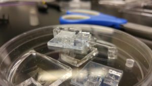
This blog post details how to assemble a variant of Jirachai’s microfluidic device (which looks like this):

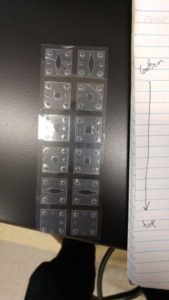
From its constituent parts (mostly this, two separate devices shown):
Cutting the Gaskets
You can find the template used to cut the 6 layers in Jirachai’s folder on the desktop mac in the computing alcove downstairs. The file is labeled designforkarl. The gaskets are cut from our standard 300 um silicone sheets. The silhouette settings are:
overcut: On, 0.3mm
speed: 1 cm/s
thickness: 20
blade height setting: 5
Leave the thin plastic sheet on top of the silicon on – it will keep the surface clean, which is important for the following bonding steps.
Bonding Successive Layers
We’ll use a microscope cover slide as the bottommost layer to give the stack rigidity. If any of your layers are dirty, they should be cleaned using IPA and/or sonication – dust and particulates can be catastrophic for the bond. Peel off the backing plastic off one side of the 2nd layer, and clean your glass. Place both, bonding side up, in the UV-ozone bonder in the corner of the lab.
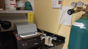
Turn the oxygen on. Set the timer for the lowest setting (15 min).
Once the ozone process is finished, carefully sandwich the layers together. Start from one edge and work your way to the other side slowly, trying to minimize bubbles. It’s most critical that the ports align.
Once the layers are together and bubble-free, put the device in the 70C oven for 30 min. Then repeat with the next layer.
We’ve used this method of bonding for some time, and it’s pretty robust. It didn’t work in this particular case (more info below) but Jirachai told me that in 20+ devices he’s never had a leak between two bonded surfaces.
Adding Ports
To create the 7mm x 7mm squares which are used to support the fluid inlets/reservoirs, pour a layer of PDMS 5mm thick in the bottom of a petri dish. Use a razor blade to cut the 7mmx7mm squares. Punch fluid inlets using a flat-head needle:
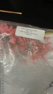
or punch a reservoir using Henry’s #2 brass cutter thingy (18 gauge):

They are attached using the normal UV-ozone bond.
If you are adding electrodes to the top, carefully poke them into the sides of the reservoir now. Seal reservoirs with scotch tape.
My variation:
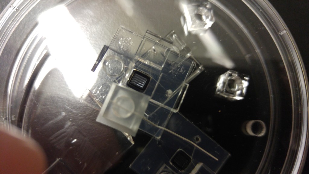
I used a slightly different method to attach electrodes directly to the chip, since I’m trying to use the embedded chip for ACEO:
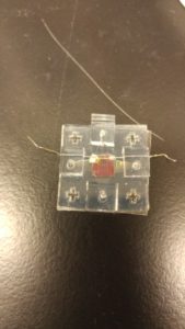
I had two problems with the device. The first was that I used Ag interdigitated electrodes for the first time, and as what I think is a result of that I didn’t see any ACEO at all. The second was that there was a leak around one of the wires in my system:
By tweaking the geometry of the gasket stack slightly I think I can fix that.
Very detailed post! I like how that #2 is used (not 18 gauge though, but do punch a 5.5mm hole i think). In honor of the current most frequent user, we should call it Jirachai or Tejas #2 from now on.
Henry