Unqualified Engineering: Modifying ALine Devices For Vaccinia Virus Capture
Since the arrival of ALine devices on the diagnostic scene during the SARS-CoV-2 sensor project, much of my effort has been focused on getting them to work properly with biological targets. With plenty of data showing successful operation of these devices with beads and several failures with SARs-CoV-2 surrogate particles, we have switched our focus towards the capture of the large virus Vaccinia. In addition we have switched our affinity-based capture approach so that we no longer coat our membranes in antibody. Instead we pre-mix streptavidin conjugated antibody with our sample and then inject the antibody bound target into a device with a biotin coated membrane. Together these changes have resulted in the successful operation of modified ALine devices, modified with my very own amateur engineering.
Vaccinia Virus
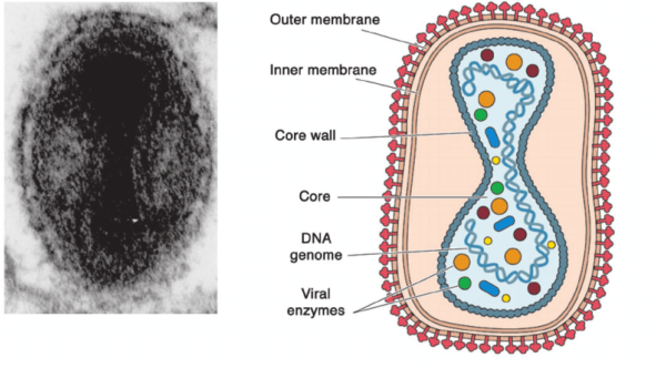
Vaccinia is a large enveloped virus which is roughly 300 nm in size. An electron microscope image and schematic of the virus are shown in Figure 1 below. Thanks to our collaboration with Dr. Brian Ward in the medical center Vaccinia and an antibody for it are readily available to us. Both are abundant in his lab and the virus is made safe via ethanol fixation. The antibody he provides us targets surface glycoproteins of the virus and is streptavidin conjugated using a streptavidin conjugation kit.
Pre-labelling Biological Targets for Affinity-based Capture
To eliminate the uncertainty and variability of new and ever changing biological target binding systems with their respective antibodies, we altered our approach to add a level consistency in our devices. Using our already well research biotin-streptavidin affinity system with beads and biotin coated membranes as a model, we replicated the system with vaccinia by streptavidin conjugating antibody for its surface glycoproteins. With the antibody streptavidin conjugated, we premix with vaccinia and coat our membranes with Kode Biotin. Using this setup we can then inject the streptavidin conjugated antibody bound vaccinia into our device where capture will occur between the streptavidin on the antibody and the biotin on the membrane. This is illustrated in Figure 2 below.

With this method in place we can easily capture other biological targets by keeping the biotin-streptavidin system in place and only change the antibody.
ALine Device Modification
Between the SARS-CoV-2 work and the Vaccinia work we acquired a new batch of ALine devices which did not perform the same as the batch we had for the SARS-CoV-2 work. I determined this after the same bead work we did with our first batch (steric and affinity capture) did not provide the same results with our new batch. With no design changes between the two batches, I believe the difference in performance must have been due to design tolerances with ALine manufacturing. The difference in performance seemed to be due to a change in the balance of resistance between the bottom channel exit port and the path through the membrane into the well. The bottom channel seemed to be less resistant than the well path (fluid would preferentially flow out of the bottom channel exit port), so to fix it I took a page out of Sam and Dans book and shrunk the exit port size by attaching a tube “plunger”. This involves inserting 1/32″ PEEK tubing with a 250 um inner diameter into a sticker rubber bumper provided by Fernando for his PETL devices. This modification is shown in Figure 3.
With this modification it seemed the bottom channel resistance became too high, fluid would almost never go out the bottom channel exit port even with a high concentration of 500 nm beads which should clog the pores of the membrane physically. To fix this I used larger 1/16″ PEEK tubing with an inner diameter of 750 um. Using this tubing with the sticky rubber PETL bumpers did not provide a continuous channel path from the device to the tubing since the tubing was larger than the exit port itself. To fix this issue I drilled out the exit port of the top piece of the ALine device using the drill press in our lab and a 1/16″ drill bit. This allowed 1/16″ tubing to fit perfectly within the exit port of the ALine devices, shown in Figure 4.

With this setup I noticed we seemed closer to the resistance balance we previously had between the two paths of the device. With a bit of trial and error I found that the bottom channel resistance could be tuned with the height of the exit port tube.
Modified ALine Device Calibration and Vaccinia Control System Formation
With a way to change the resistance of the bottom channel established, I worked towards setting the device up so that it could work properly within the range of concentrations we desired. Relying on our past work with beads for steric and affinity-based capture confirmation, I set out to try to get reliable switches with beads down to 10^5 beads/mL. Calibrating the device with 500 nm beads and 200 nm streptavidin coated beads with uncoated and biotin coated 500 nm slit chips respectively, I found that a tubing height of 8 mm set the device resistance so that a resistance switch could be activated at a concentration as low as 10^5 beads/mL without having PBS alone trigger a switch. A positive switch in these videos is indicated by a droplet coming out of the exit port tube and falling off onto the device. Each test I injected 40 uL of sample. These results are shown below in Videos 1-3.
Video 1: PBS – Negative Control
In this example a switch should not be triggered since there is nothing in the sample that would clog the pores.
Video 2: 500 nm Beads – Positive Steric Control
In this example a switch should be triggered since the beads will physically occlude the pores of the membrane.
Video 3: 200 nm Streptavidin Coated Beads – Positive Affinity Control
In this example a switch should be triggered since the beads will occlude the pores via affinity-based capture.
With these controls in place, I set out to test Vaccinia capture using our pre-labelling system described above.
Vaccinia Capture Using the Modified ALine Devices
For Vaccinia capture I mixed 10^5 virus/mL solutions with 100 uL of 1 ug/mL solutions of antibody. I allowed these mixtures to interact for 1 hour at 4 degrees Celsius before injection, and injected 40 uL of sample for each test. The results are shown below in Videos 4-6.
Video 4: Vaccinia with Vaccinia Antibody – Test Group
The result of this video is similar to that of the beads in our control tests. This implies that the pores of the chip are being occluded enough by antibody bound vaccinia to trigger a switch.
Video 5: Vaccinia – Antibody Control
This video shows a partial negative switch. More of a switch is triggered than just PBS, but not enough of the membrane is occluded to trigger an actual switch. I believe this partial switch is caused by vaccinia aggregates.
Video 6: Vaccinia with Rabbit Antibody – Antibody Specificity Control
This video also shows a partial negative switch which I also believe is caused by vaccinia aggregates.
Overall the results seemed to show that the device is indeed working properly with vaccinia virus. To cut down on the partial switches in our control groups, I decided to pre-filter the mixtures to see if these partial switches could be eliminated.
Pre-filtering Vaccinia to Limit Nonspecific Aggregate Occlusion
Taking the pre-labelling method a step further, an uncoated membrane with the same size pores can be used upstream of the coated membrane to filter out anything that would clog the coated membrane physically. This is shown schematically in Figure 5 and results in the coated membrane ideally only seeing things smaller than its pores for capture.
In practice, these results are shown in Videos 7-10.
Video 7: PBS – Negative Control
Just as before nothing in solution occludes the pores of the chip to trigger a switch.
Video 8: Pre-filtered Vaccinia with Vaccinia Antibody – Test Group
Pre-filtering reduces the response of antibody conjugated Vaccinia, but compared to the control groups it still has the greatest switch overall.
Video 9: Pre-filtered Vaccinia – Antibody Control
Pre-filtering all but eliminates the response of this control group.
Video 10: Pre-filtered Vaccinia with Rabbit Antibody – Antibody Specificity Control
Pre-filtering also limits the response of this control group.
Future Work
After pre-filtering, the performance of the device is greatly improved. Moving forward the device performance can be improved even further depending on what kind of resistance switch we would like to see to make a better distinction between a positive and a negative test. We would also like to complete some combination experiments with fluorescent imaging and with PCR confirmation of virus capture.