TEOS vs. Thermal Oxide
This week, we explored the possible differences a thermal oxide making layer had versus a TEOS on membrane morphology. Here’s what we found:
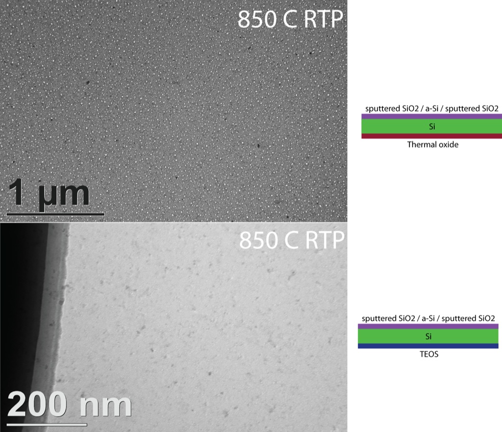
The top image shows wafer 410 @ (1,0) and the bottom wafer 503 @ (1,0). Both wafers were annealed, cleaned, sputtered using the same conditions. The only difference was the masking material. Even at a high mag, wafer 503 does not show any open pores whereas wafer 410 has pores ~ <20 nm>.
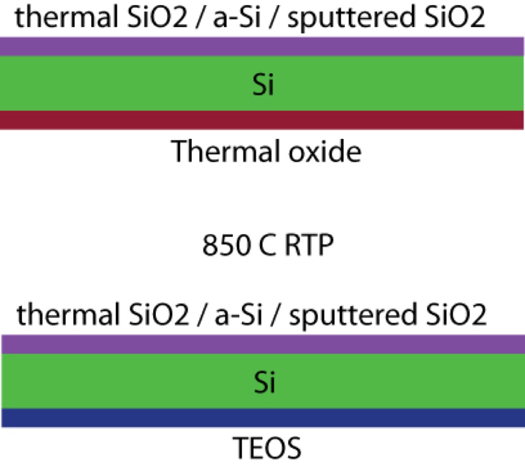
I also noticed a slight non-uniformity for both wafers. I think we can conclude that the initial thermal oxide that we put down on the front-side contributes to pore uniformity and aids the formation of pores. The next step would be to produce wafers like this:
For the record, Jess and Karl both found evidence of open pores in 503, although the porosity was low. I’m sure they’ll post on it. You didn’t give your theory for how the front side impacts pore formation.
The image I showed of 503 is an inside sample. I did find a small number of very small pores in some of the outer membranes…
My thought is that thermal oxide is stressed more than TEOS films. This additional strain may aid in pore formation, which is why we see pores in the thermal wafers but not in the TEOS for identical process conditions. Furthermore, a frontside thermal oxide in conjunction with a TEOS backside mask has given us the best results w.r.t. uniformity. This makes sense because we have a low stress film on the backside so that the frontside oxide becomes the dominant player.
Jess and I actually tested W501 not 503 (yet); air permeability results for W501 can be found here
https://trace-bmps.org/datablog/2008/04/25/w501-air-permeability/.