Spot the Difference: Testing the Spatial Resolution of the Andor Dragonfly Confocal Microscope Using GFP Tagged Staphylococcus aureus and Nonporous Membranes
While imaging GFP tagged Staphylococcus aureus on our membranes within µSiM-CA devices, the question of whether or not we can differentiate between bacteria on the top and bottom of the membrane versus within the membrane has persisted. We know that during our experiments bacteria exist in all three of these places, therefore the question really is whether or not the confocal microscope has the spatial resolution to resolve this. In one of our first visualization experiments, described here, we attempted to gauge our ability to do this by comparing 4 slot flat nonporous membranes to porous 0.5 µm microporous membranes. Unfortunately, our results were inconclusive and we were unable to definitively say whether or not we had this ability. Recently, we received two new types of nonporous chips. The first contained square, flat nonporous membranes. The second contained three rectangular (3 slot) membranes which had 500 nm diameter pores with floors (dimples/wells) in a hexagonal array across the entirety of the membrane surface. Our hope was the floor in the bottom of the pores in the dimpled membrane would provide a noticeable line within the membrane where fluorescent bacteria could settle into, thus providing us with a way to more definitively determine if we could actually see bacteria within the membrane. Our approach and results are described below.
Methods
Preparing the µSiM-CAs for Testing and Loading them with Bacteria
- Ahead of time, prepare Tryptic Soy Broth (TSB) by adding 30 g of BBL Trypticase Soy Broth to 1 L of purified water
- Mix thoroughly and warm gently until powder is completely dissolved
- Autoclave at 121°C for 15 minutes
- Start an overnight culture by scraping up a chunk of glycerol stock with a pipette tip and adding it to 2 mL of TSB
- Take this overnight culture and put it into a shaker, shaking at 37°C overnight
- The next day, create a subculture by adding 1 mL of your overnight culture to 100 mL of TSB
- Put the subculture in a shaker and let grow at 37°C while shaking until it measures an OD between 0.2-0.4 (I used OD 0.269 for this)
- While the subculture is growing, thoroughly examine each µSiM-CA device you will use for any defects such as improper sealing between components or broken membranes
- Prepare petri dishes to hold µSiM-CA devices by placing 2 Kim Wipes moistened with sterile dH2O along the perimeter of each petri dish
- Pipette ~15 µL of TSB media by inserting the pipette tip into one of the two open ports of the µSiM-CA and depressing the plunger of the pipette; the media should flow from this port through the bottom channel and out the opposite, open port. Remove the pipette tip before releasing the plunger of the pipette to avoid sucking injected fluid back out of the bottom channel of the device
- Fill the well of the µSiM-CA by pipetting 100 µL of fresh TSB into it; care is taken to not create air bubbles and/or remove them by by withdrawing injected media and injecting it again until no air bubbles are visible
- Remove all liquid from the well (~100 µL)
- Next, add 100 µL of the desired OD subculture to the well of each device, withdrawing and injecting the subculture again if air bubbles are present until they are gone
- Allow the devices to incubate at 37°C for 6 hours
After loading, I imaged the devices using a confocal microscope and the method described below.
Confocal Imaging µSIM-CA Devices Containing GFP Tagged Staphylococcus aureus
- PDMS blocks (~5 mm thick) were laid on top of loaded µSiM-CA devices in order to allow them to be imaged in the microscopy core while maintaining gas permeance
- Any liquid pushed out to the sides of the device is wiped away with a Kim Wipe
- To create an adequate seal, the interface between the PDMS bottom and the acrylic top of the device was sealed with nail polish
- Upon sealing, devices were stored in petri dishes filled with wet Kim Wipes for transport over to river campus
- Once at the microscopy core, images were taken with the 60X water immersion objective (1.2 Numerical Aperture). The 488 nm laser was used with the 525 nm filter
- While imaging, devices were stored in an incubator stage attached the confocal microscope which is held at 37°C
Results
SEM Images
To visualize each membranes surface morphology, I took SEM images of their surfaces. Figure 1 below shows an image of the nonporous membrane we previously used for visualization as well as images of the two new nonporous membranes that I used in this experiment.
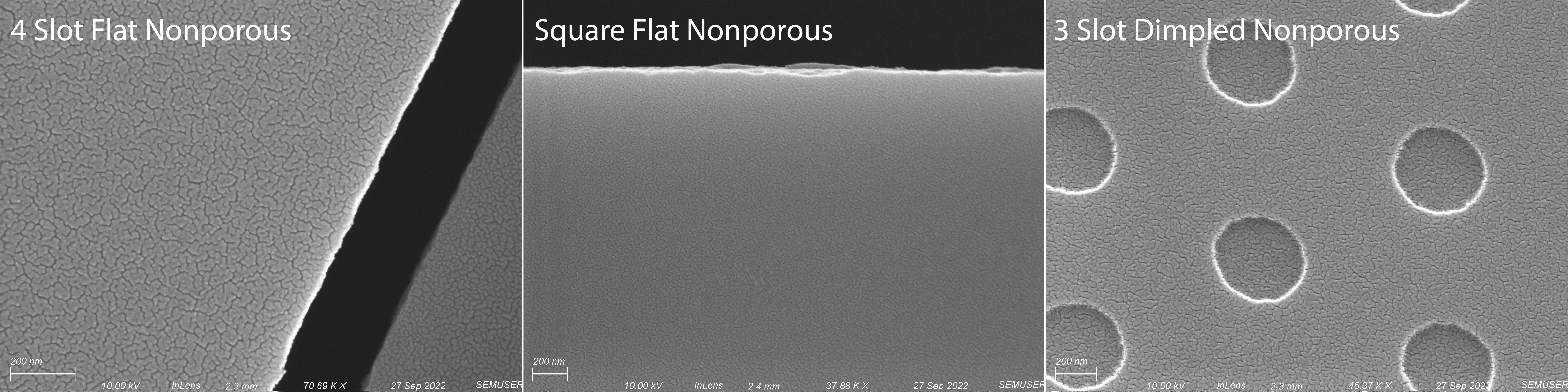
As expected, both flat nonporous membranes are indeed flat while the dimpled nonporous membrane has 500 nm diameter circular dimples with a silicon floor. With visual confirmation of surface morphology, we moved on to building both the square flat nonporous and 3 slot dimpled nonporous membranes into devices to test with GFP tagged Staphylococcus aureus.
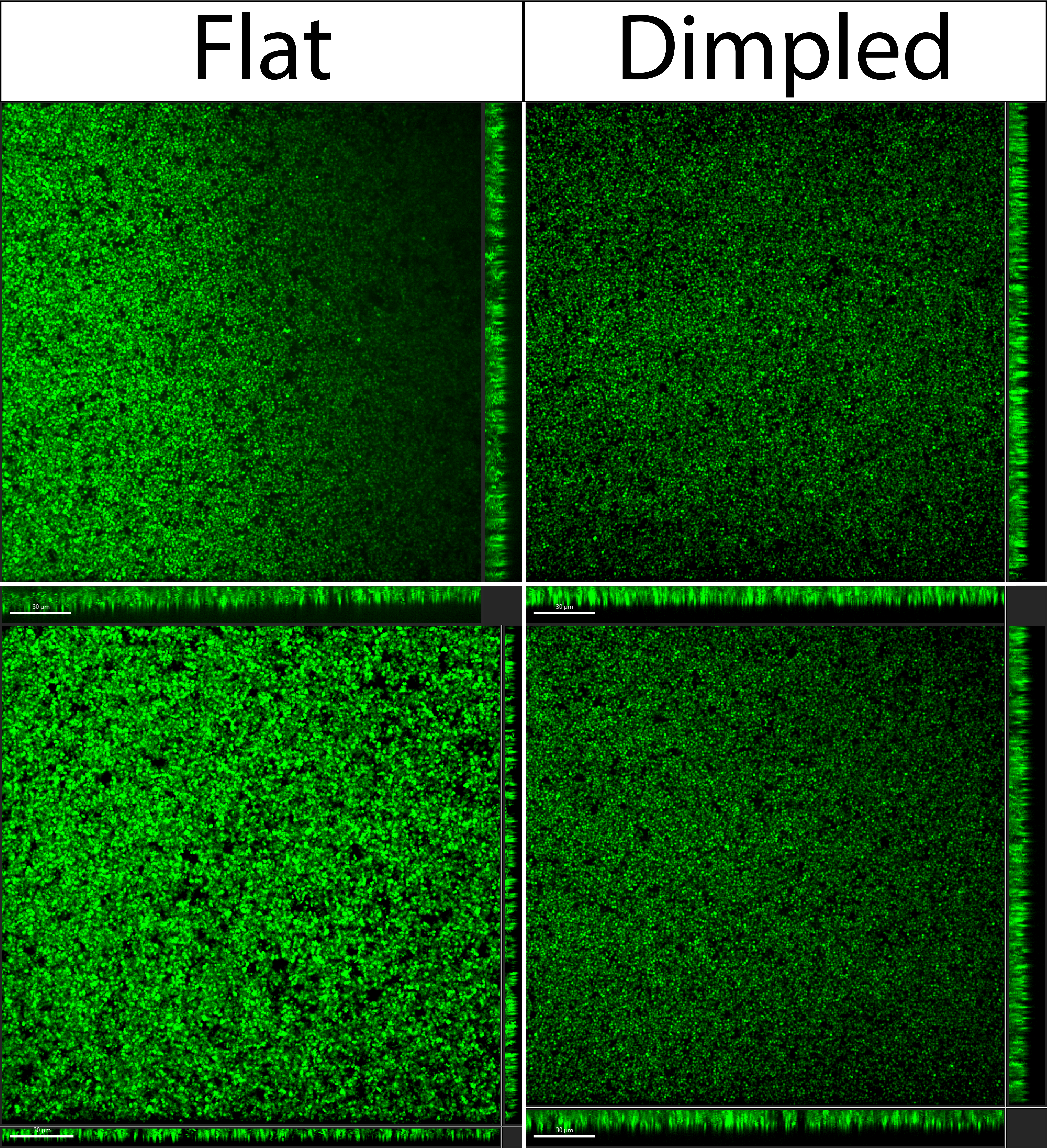
Confocal Images
After loading assembled devices with GFP tagged Staphylococcus aureus, it was very difficult to discern any differences between the flat nonporous membranes and the dimpled nonporous membranes. Shown in Figure 2 below, GFP tagged bacteria laid across the surface of both membranes evenly when looking from the top down onto the membrane. From the side bacteria seemed to also lay evenly on both membranes.
A closer look at the side views from Figure 2 are shown in Figure 3 below.
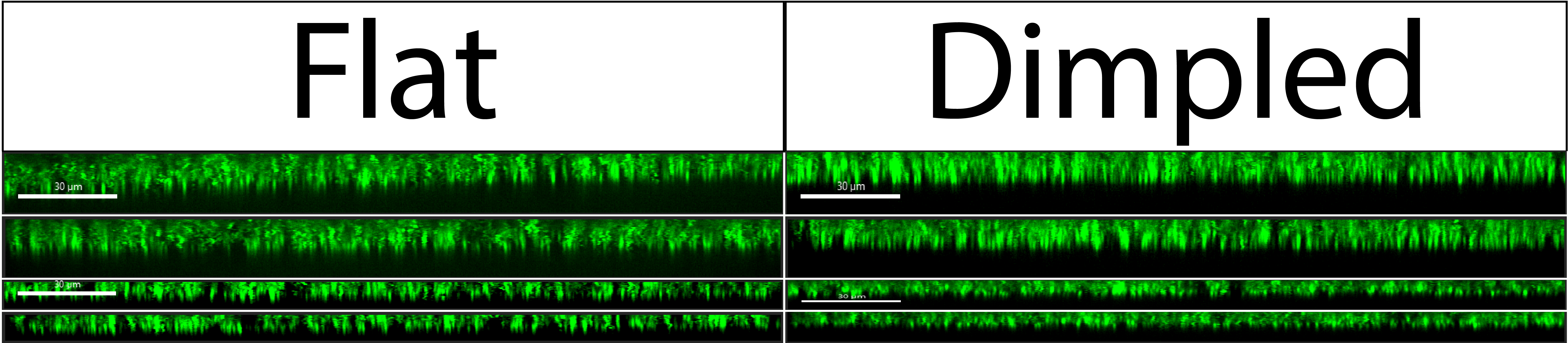
Regardless of which type of nonporous membrane image we look at, the side views show bacteria laying relatively flat. We can reasonably assume that if there is bacteria all across the surface of the dimpled membranes, there should also be bacteria in the bottom of the dimpled pores (on the floor of the dimples/wells). Since we cannot see this in our images, we can conclude that our current setup on the confocal microscope does not have the spatial resolution to resolve such minute differences in bacterial position on the membrane.
Conclusions and Future Directions
Currently, we do not have the spatial resolution to differentiate between GFP tagged bacteria on the top and bottom of the membrane versus within the membrane. To address this moving forward, a change has to be made to the confocal system in order to increases its spatial resolution. The easiest change would be to obtain an objective with a higher magnification and or numerical aperture, otherwise other hardware changes could be made to the scope related to its lenses or camera.